Category Archives: Joinery

Table Legs & Terrific Technique

IMG_1883The LVL desk build continued with the legs. I milled 8/4 material, then joined two pieces to form four 3-1/2″-square legs. Square wouldn’t do, so we decided to taper the 28″ lengths over 24-1/2″, leaving a bit of square at the top. Tapering legs is best done at a jointer, if you ask me. As long as you hit your layout lines, you can nail each leg so that they are all tapered exactly. It took only minutes to taper all 16 sides.

Still, the legs didn’t have the right look, so we decided to chamfer the corners. But how do you stop the chamfer at the perfect location? You don’t. We trimmed the corners along the legs entire length; that left the square portion at the top end tapering out of the cut made at the router table.

IMG_1885To join the legs to the top, we went with a simple idea – dowels. If we would thought of this at the beginning, we could have drilled the leg ends while the blanks were still square. But, of course, we didn’t, so the set-up was a bit more involved. I rotated the table on my drill press, clamped a straightedge in position then centered the 1-1/4″-diameter bit in the leg, which was clamped to the straightedge. (Told you it was more involved.) Holes were drilled about 1-1/2″ deep because the arm of the press came down onto the rotated table to stop the cut. That wasn’t enough of a hole in my opinion. Afterward, each hole was set another 1-1/2″ in depth, and dowels were glued in.

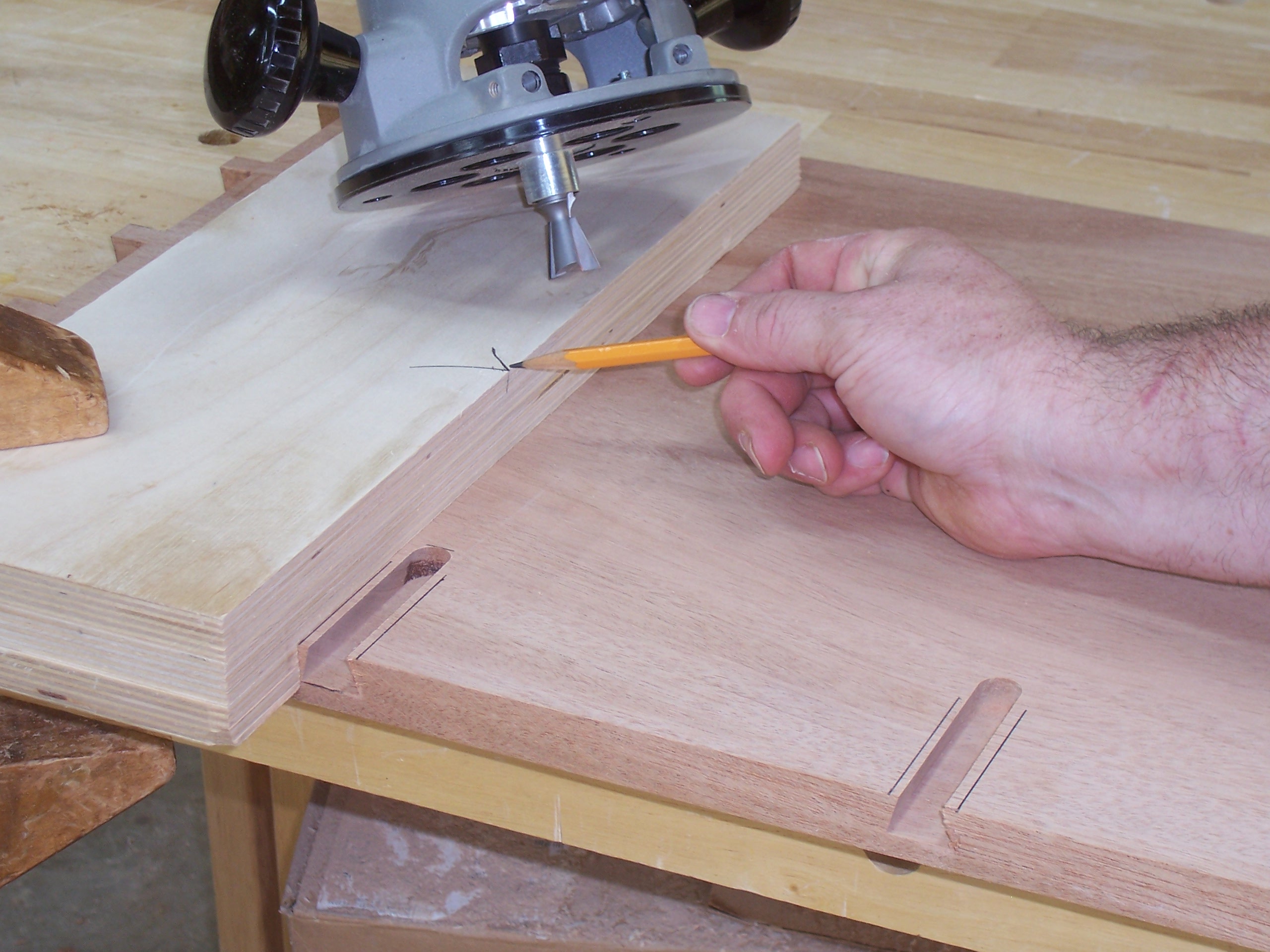
For each leg to fit tight and flush with the bottom surface of the tabletop, it was imperative that the 1-1/4″-diameter holes drilled through the top be square to the large flat surface. IMG_1892There’s no better tool than a router for this work. I don’t, however, have a router bit that diameter, so there was no way to plunge the holes as you would when knocking out adjustable shelf pins. The next idea worked perfectly. drill through the top in the correct location using a smaller diameter drill bit (in this case I used 3/4″), then enlarge the hole using a top-mount pattern bit. All that’s needed is a scrap piece of plywood with a hole drilled exactly to size; that’s easy with the drill bit already in the press.

IMG_1891To use the jig, clamp the plywood piece in position on the table’s top over the previously drilled hole, slip the router setup into the hole with the bit’s bearing riding along the plywood cutout and rout a perfect matching-size hole in the top. To get through the entire 2″ of top, we had to remove the plywood and repeat the steps using the trimmed portion of the hole as a guide. Easy, peasy!

IMG_1897With the holes drilled and the dowels sawn for wedges, we slipped the legs into the top, spilled a little glue into the sliced dowel then drove walnut wedges to bring everything tight. The final look with the dowels and wedges trimmed look good. Plus, there’s no wobble in the table, especially after the glue dried.

Build Something Great!

Glen

Leave a comment

Filed under Design, Desk Build, Jigs, Joinery, Methods of Work, Shop Tips

No Day to Spray

AntiqueBackWhen I got up on Saturday morning, I knew there was a huge possibility that in the shop I wouldn’t be doing what I planned. I was going in to spray the final coat of shellac onto my clocks; I’m looking to darken the overall appearance just a shade more. The humidity was high which means that there was a chance for the finish to blush, or turn cottony white with moisture trapped in the finish.

Instead, I decided to work on the backboards for the two clocks. On most antique clocks, the backs run top to bottom and are not attached to the hoods, so the hood can be removed. The stacked series of three photos at the left show a typical clock back (click on the image to make it bigger).

Generally you see a main board that runs the full length with ears attached at the base and hood areas. That requires a board or panel that’s 90″ in length and 15″ wide. I could have done that – may due it if John and Joe (brothers for which I’m building this clock) want to go with the antique design.

The second clock, however, is for me (at least at this time), so I’m going at it differently. IMG_1767I’m running the boards across the back from the bottom up about 50″ just as would be seen on a case piece of furniture. I then plan to turn the upper board so its grain runs vertical. To make the transition, I’m using a tongue-and-groove joint. It’s a bit more work and will need a few additional fasteners (nails I suspect), but I can use short pieces of scrap cut off from other projects. Frugal, huh!

To make this happen, I first added a shiplap cut to each of the milled, over-long, random-width boards selected for the back. IMG_1768
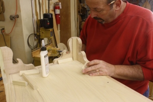
I began at the bottom – the bottom board was cut on only one edge. From there to the 50″ mark (it doesn’t have to be that length, it’s just what I chose based on the number of pieces I had to use and the width of those pieces), I fit and positioned each board. The top board – also shiplapped on one edge – was taken back to the tablesaw for the tongue portion of the transition joint. I then slipped the top horizontal board in place and added a couple of clamps to hold things secure.

IMG_1771I had to get the final length measurement of the vertical board, so I had to stand the case upright and add the hood. With that measurement in hand, I cut the groove portion along the bottom edge of the panel, and laid out the exact spot where the back needed to step out to fill in the extra width of the hood.

Because the glued-up panel had set in the shop for some time,there was a small amount of warp I had to deal with. Here’s a great shop tip: To straighten out the panel, I clamped a straight piece of stock across the panel width keeping the clamps above the height of my saw fence, then made the cuts needed to form the groove.

The ears were cut at my band saw, then trimmed to length at the bench using my handsaw. To final check and tweak the fit, I joined the tongue and groove, then slide the assembly into position. Below you can see how the transition works. Because the top panel extends down the clock’s case, there are more than enough places for fasteners. This setup should work great.

Build Something Great!

Glen

IMG_1775

1 Comment

Filed under Design, Joinery, Methods of Work, Shop Tips, Tall Clock

Karen’s Inlaid Box

Karen_DogsWatching shellac dry is not much fun, so as things progress on the tall clocks I decided to knock out a promised-to-build, small box. It is close in design to the tea caddy I built for a magazine article a couple of years back. This box doesn’t use edge banding, so the work is a bit easier. The artist rendition (actually my drawing from SketchUp) looks too red; I’m building the box out of mahogany and using tiger maple for the trim pieces. I’m writing about this not so much for the value of the project, but more for the techniques I use as I build – there are methods used that can be employed on other projects.

The four horizontal parts of the box were milled to size and thickness. I made the pieces 1/2″ thick; width and length are your call if you’re building along. The first big step is to bevel the ends of each piece, and you know there are many different methods you can use. I choose the table saw for a couple of reasons: IMG_1656It’s easy to use, I can set up the miter gauge to be square and once the blade is set to 45°, I can use the same setup for two operations. The photo (at right) shows the setup used to bevel the ends. A sacrificial fence with a cut ran through it after the blade was beveled, makes it easy to locate the box parts to trim. I also added a stop-block to keep the parts from creeping away from the blade as the cut is made. One additional point you should glean from this image is my hand placement. My first inclination was to grab the gauge with my right hand and hold the part with my left. If that happened, my left arm would – at some point in the cut – completely block the blade from my view. That’s not good.

The next cut to make is for a spline to run up the corners. I learned a long time ago that making a 45° cut into a previously cut 45° bevel results in a cut that’s 90° to the bevel cut. (What did he say?) IMG_1657Using the same table-saw setup but placing the gauge on the opposite side of the saw blade, makes the next step cake. Once again, make a pass over the blade to establish where the cut hits the sacrificial fence to use to align the parts, then position one piece to that kerf. Make sure to dial back the blade height, then clamp a stop-block in position to use as a guide for each cut. Notice how I switched my hand placement for this round of cuts.

IMG_1658I’m going to set the box bottom inside the four horizontal parts, so I need a groove cut along the bottom edge. Many woodworkers would gravitate to a dado stack for this step, but to me, this is a waste of time. A couple of passes with the blade set to the correct height and the fence properly positioned and you’re done with the groove. Easy, peasy. And there’s no need to swap blades.

The action is picking up. Next step is the bottom. This I made from tiger maple. (Yes, I know you’re not going to see the bottom most of the time, but I have so much scrap tiger maple around my shop it’s a crime not to use the smaller cutoffs for something.) IMG_1661To rabbet the edges to fit into the roughly 1/4″-wide grooves, I use a two-step method at my table saw – what can’t you do with this machine? The process is straightforward. After you get the necessary measurements from the box parts – you can measure the width and length right in the grooves of the front and end – cut the bottom to size (you may want to go a bit less in width to accommodate for any seasonal movement if your box is on the wide side. The first pass is with the bottom face down against the table top – set the blade height to leave a 1/4″ of material after the cut. I make a 3/8″-wide rabbet to make sure the edge doesn’t interfere with the box as it goes together. The next step is to readjust the blade height to just tick the top edge of the previous cut (with the part standing on edge at the fence), and to set the fence to leave the tongue thick enough to slide into the groove. While it doesn’t make much of a difference here, it’s good practice to run the end-grain cuts first.

IMG_1662After you cut pieces to fit into the spline cuts, it’s time to assemble the box. Two points to make here: Your splines cannot run from top to bottom – you need to stop them at the groove or your bottom will not fit, and only assemble the box at two of the four corners at the beginning. If you do glue all four corners, make sure you install the bottom as you assemble the parts. I like to glue half the box, then slip in the bottom and finish the assembly later. Working all four corners and the bottom at the same time can get busy. Add a few clamps and set things aside.

After the glue dries, slip in the bottom, add glue to the remaining splines and corners, then put the clamps back in position and let it set.

IMG_1664

In a later-to-come post, I’ll add a top to the assembled box, split the lid off the base then add some trim pieces. After that, I’ll make the fan inlays to complete the box.

Build Something Great!

Glen

2 Comments

Filed under Joinery, Methods of Work, Power Tools

Different Blade Connection

6-Dr_Chest_Complete-1Wonder what blades are? It’s simple. In furniture speak, blades are another name for drawer dividers. As you probably know, there are many techniques and joinery methods to attach drawer blades to the case. The technique shown here is one that is not all that common, but it is found in antique furniture, namely the Moses Bayley high chest of drawers from Newberryport, Mass. (There is a fascinating bit of history surrounding the highboy; read more about it here.)

In the first issue of American Woodworker magazine under the complete guidance of F+W with me as the content director, I built a chest of drawers (shown above) using this blade connection technique – the issue should be available sometime in early June. (You and 100,000 of your closet friends should pick up a copy!)

B_SlotThe process is easy. While the connection could be done without plowing an 1/8″-deep groove, it’s easier to do so and the groove adds another detail to your work. Step #1 is to rout the groove – align a straightedge to your project, then run a router and 3/4″ top-mount bearing router bit along its length as the bearing rides your straightedge. The width of the groove has to match the thickness of your drawer blades.

Step #2 is to form the dovetail on the ends of your blades. The length of the dovetail – how high you need to raise your router bit – is equal to the thickness of the material remaining after the groove is cut. A_DovetailIf you’re using 3/4″-thick material, after the 1/8″ groove you have 5/8″ of thickness remaining. For me this is a bit of work completed at the router table. Set the height of the bit then adjust the fence so its aligned with the router bit exactly at the table’s top edge. This takes advantage of the entire thickness of your blade – if you’re slightly thinner after your cut, that’s OK, but do not leave a flat on the edge of the dovetail. (Notice the solid push block used to guide the tall drawer divider through the cut.) After you have the dovetail ends created, cut away the back edge leaving a 1″-wide dovetail – trim the dovetail away flush with the square shoulder on your blade.

C_LayoutStep#3 is to transfer the dovetail profile onto your case side. As you can see in the photo, the blade slips into the groove and the trimmed dovetail sits tight to the case side. Using a sharp pencil, transfer the profile. Nothing fancy here. No special details to share. Simply install the blades into position then draw the lines. Bingo.

Step #4 is to square the layout lines down the case side 1″ (matching the dovetail width), then draw a straight line setting the bottom of the socket. D_SawIt’s time to define the socket. This is where your ability to saw comes into play. Cut the two sides of your layout down to the inch mark. Follow both lines as you saw. After you’ve established the socket’s outer edges, make a few additional saw cuts between the lines – the more kerfs you have, the easier the next couple steps become and the cleaner your socket will be to work.

Step#5 is to break out the thin pieces of wood that fill your socket. E_PareYou can jam a chisel into the slots, or if they’re thin enough, you can break the pieces out with your fingers. The neat things is that when they break – due to the grain orientation – the slivers break flush with the bottom edge of the socket. (Sometimes they do break slightly above the line.) With the pieces out of the way, pare the socket bottom so it’s smooth and level. Make sure the socket is level from outside to inside. And it wouldn’t hurt to slope a bit toward the inside – that guarantees you’ll have a tight fit on the exterior of your case.

The last step is to fit the blade’s dovetail into the socket. F_FitIf you’ve sawn to the layout lines and trimmed the socket even at the bottom, your blades should fit easily. Brush glue onto the dovetail and into the socket (the best glue surface is the flat-grain to flat-grain connection at the bottom of the socket), then drive the workpiece home. By the way, don’t forget to repeat these steps twice for each drawer blade or divider. Test-fits are terrible with only one socket cut.

I’m not going to show you a finished shot of the chest of drawers – for that you’re going to have to wait until the issue is sent – but I will show you a photo of the highboy mentioned above. In fact, if you’re so inclined to want to see this process in action, I have a full-length DVD on building the Moses Bayley chest. You can purchase a copy here.

Build Something Great!

Glen

G_MA High Chest

2 Comments

Filed under Antique Pieces, Hand Tools, Joinery, Methods of Work, Power Tools, Routers

3 Accepted Foot-to-Case Connections

Last week, after I professed that everyone should have a spindle sander, A few readers asked how I used a spindle sander as a thickness sander. It turns out that I have posted that technique, but it was inside another post. Here’s a link to that post; you’ll find the spindle sander being used to thin ebony string about halfway down the post.

Entertainment_Center copyOn to the next topic: How to attach feet to your case. Of course, there are a few ways to get feet on your cases. There are three methods I generally use on most every case. The first is to attach the feet directly to the bottom of the case, a second method is to rout the top edge of the joined feet and install a plate through which screws affix the assembled unit to the case bottom and the third method is to attach feet to a frame then attach the frame to the case and use a transition molding to cover the through dovetails where the case bottom joins the sides. I mention other methods, because I’ve built a couple of chest – full-size and spice boxes – from Chester County where the feet were attached directly to stiles of the frame and panels sides. While this is not commonplace, it, along with other methods, is sometimes done.

To attach feet directly to the case, I begin by installing a molding to which the feet are glued. You wouldn’t think that you could assemble feet to a molding and that would be strong enough to hold everything for 200 years. IMG_1590Of course, you would be correct. What really holds the feet to the case are  glue blocks. These blocks also carry the bulk of the load of your chest. On the case I’m currently at work on, the thickness of the feet allows about an 1/8″ of the feet to lap onto the case itself. Then, with the glue blocks in place, the weight of the case is divided on the actual feet and on the glue blocks – the vertical block holds the weigh while the two horizontal blocks keep the assembled foot attached.

The next method is a bit more work. And the added plate makes the connection easier, but not necessarily any stronger. After the two foot pieces are joined via miters, I rout a small lip on the inside of the feet using a rabbeting router bit to which I attach a thin plate. Plate
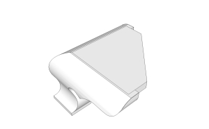
The SketchUp drawing at the left shows how the plate fits to the feet; a thin bead of glue and brads secure the plate to the feet. The assembled unit is then screwed directly to the case bottom with the unit sticking out in front of the case. The look is completed by wrapping a molding around the case. An example of this type of connection is seen in the opening photo, although you cannot see the plate. That’s by design. As you see in the drawing, the cutout for the plate does not blow through the end of the foot.

The last method – the option that I find the most used as I look back at furniture I’ve built throughout the years – is to attach the feet to a base frame which is then attached to the case. Foot&Frame3
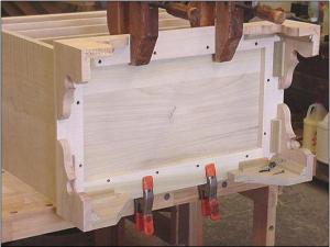
I used this method on the Pennsylvania blanket chests in the August 2009 issue of Popular Woodworking Magazine (#177) and the Serpentine chest from issue #195 (February 2012). As you can see in the right-hand photo, the same idea of glue blocks is used – mainly for reinforcement in this case. The frame is attached to the front of the chest with screws, but the remaining frame is nailed to the case bottom to allow for seasonal adjustments. The look is then completed with a transition molding.

These are three good methods used to attach feet to cases. There are pros and cons to each, as there is with any technique used in woodworking. Whenever you here, “This is the only way to do it,  run in the opposite direction. You have choices.

Build Something Great!

Glen


3 Comments

Filed under Joinery, Methods of Work

The Best Dovetails

If you came here looking for the perfect set of dovetails – the best layout, the best ratio of tail width and pin width or the thinnest pins ever cut – you’re going to be disappointed. This post is not about that. It’s about dovetails that are never to be seen. It’s about what I call structural dovetails.

IMG_0084Structural dovetails are the best dovetails because these joints can have over-sized tails and pins, and this is where you get the opportunity to either bang out a set without regard to the above mentioned conditions, use alternative methods to cut and fit your joints or practice in an area that will not see the light of day – why practice on a scrap when you can contribute to your project while building your skills. For me, alternative methods of work is my focus.

This is a point where I can pull out tools that are seldom considered when cutting dovetails. Tools such as my jigsaw and router. This is where I experiment to determine if there are better ways to work – and I still move ahead on my project.

49If  you’re scratching your head at the mention of my jigsaw, or if you’ve never considered using your jigsaw to cut intricate joinery, you’re in for a treat. I often use my jigsaw to cut dovetail pins and tails. (It’s best if you turn down the variable speed setting to gain additional control of the cut.) And I’ll bet you a dollar to a doughnut that you couldn’t tell which joints were cut using the jigsaw and which joints were sawn by hand.

Let’s being with pins, or wasting away the tail waste. Jigsaw blades can be angled in either direction, and set to most any degree of angle; I use 12° for my dovetails. The photo above shows how you can make the cuts to define the pins. Set the angle to the right or left, then cut all the pins on that particular side. Switch the angle to cut the pin sides in the opposite direction. Done.

51To pull the remaining waste from the socket, it’s the jigsaw again. Set the blade back to 90°. With the show face down, swoop in from one side of the waste as you cut toward the baseline. As you reach the baseline, swing the jigsaw to cut parallel to the line but about an 1/8″ away. As you reach the end of the waste, slowly kick your saw back on its heal to increase the angle of cut until the portion of waste falls away. It takes getting used to, but you’ll pick it up in a hurry. Besides, if you nick the pin, who cares because it will never be seen. After you finish working in one direction, turn around and use the same technique to trim away the remaining waste. That 1/8″ that’s left is easily peeled away using a sharp chisel. You also can cut the pin waste using you jigsaw; I sometimes do that when the panel I’m dovetailing is too large to hoist up to my band saw.

IMG_1519

Fooling around with structural dovetails is also when I began using my router to waste away tail socket waste. If you haven’t s seen this technique as of yet, you owe to yourself to take a look. The results are dead-flat bottoms that dam near guarantee square boxes when you’re done with assembly. (Watch a short video here.)

Next time you’re working on structural dovetails – the best dovetails – try your hand at a few unconventional woodworking ideas. You may find something that works beyond your wildest expectations.

Build Something Great!

Glen


2 Comments

Filed under Joinery, Methods of Work, Power Tools

Different Dovetailed Drawers

IMG_0622The drawers on the Connecticut lowboy that Bob Van Dyke and I found in the back room of the Connecticut Historical Society are tapered from bottom to top. I’ve mentioned in blogs (either here on my blog or on the Popular Woodworking Magazine (PWM) editor’s blog) that I’ve seen this treatment of drawers only one other place, and that was on Grove Wright’s Shaker work, including the Shaker Counter I copied and built in the June 2012 issue (#197) of Popular Woodworking Magazine.

The process of making these drawers is a bit different from regular hand-cut dovetailed drawers. To begin, the material for the drawers sides and back are tapered. Because there are two drawer depths on the one lowboy, there are two different tapers needed on the drawer parts. IMG_1280I set up my band saw to just leave the bottom of the parts uncut, and the top edge to cut leaving a 1/4″.

Off the band saw, the cut faces need to be smoothed. That could be a pass over the jointer. But with the narrow edge being only a 1/4″ in thickness, I think it was best to use a jointer plane. It’s from here that things get twisted. I used my marking gauges, but not in a way that is customary when dovetailing drawer parts. I set on gauge to 1/2″ and a second to 1/4″. I used the two gauges to place tick marks at the top (1/4″) and bottom (1/2″) to use as layout lines. IMG_1282The next step – where you would normally use a marking gauge – I used a straightedge and utility knife to score the baselines.

The trick to marking off the pins and tails is to use the square or outside face as a register. (If you use the inside face, your marks can be all kind of funky angles.) After the layout is complete, it’s a matter of sawing to the lines then chopping out the waste. Because I work pins first, I began with the pins in the drawer backs. To transfer the pins to my tail board, I set the completed back in position, making sure the orientation is correct. To cut the tails, I go back to the band saw and cut just off the layout lines, inside the pin waste area. Ordinarily, I would chop the waste at my bench, but because the parts are angled – and the waste area is so narrow – I stay at the band saw and trim the waste using power. Nibble. Nibble. Each time staying just tight to my baseline. Because this is a poplar-to-poplar fit, I get a little smash factor to make it all work.

IMG_1286The drawer fronts are not tapered, but the sides are. Again, I have to use the straightedge-and-utility-knife layout method, but from there the process is the same as with standard dovetailed drawers. The only difference is the tail sockets are tapered from top to bottom. To transfer my pins to the tail board (drawer sides), I set the front at my scribe lines, which is a consistent 1/2″, then transfer the lay out.

In the drawers of the Shaker Counter, the bottom was slid into the 1/2″ thickness of the bottom edge. The lowboy drawer bottoms at applied – it’s good to have the thickness at the bottom for nailing. I use the counter on a daily basis, and the drawers slide spectacularly. I’m wondering if it’s the design (heavy bottoms) or the yellow pine I used for drawer parts. I’ll have a better picture when the lowboy is wrapped up.

Build Something Great!

Glen

This lowboy is an upcoming project in Popular Woodworking Magazine. To see the entire project, pick up the February 2014 magazine – if you’re not a subscriber.

4 Comments

Filed under Antique Pieces, Joinery, Methods of Work, Shop Tips

Screw Gains

“Their usual solution was a pair of large screws driven forward through the side rail into the front leg to supplement the hidden mortise-and-tenon joint. Each screw fits into a drilled and carved out ‘pocket’ or ‘screw gain’.”

IMG_1248Immediately as I mention pocket screws, many woodworkers’ eyes roll back into the heads as if this method of joinery is totally unacceptable. Of course, there are places where the use of pocket screws is not the best choice. There are also places in woodworking where the joint is the perfect solution. It’s up to us to know the difference and where to draw the line.

But the more you discover about pocket screws, the more fuzzy the line becomes. I’ve been in million-dollar homes, standing in kitchens that easily cost six figures, and the face frames on the cabinets were pocket screwed. Perfectly acceptable? You betcha. But that’s not furniture, right? No it’s not, but the quote above is about furniture. It’s about great furniture. Museum-quality stuff. The quote is taken from the book by Robert D. Mussey Jr. titled, “The Furniture Masterworks of John & Thomas Seymour.” The Father and son team used pocket screws. This method of joinery is not a new concept conjured up by the Kreg company, but it has elevated pocket screws to a whole new level.

The reason I write about pocket screws this morning is that I have a decision to make on the lowboy I’m building based on the piece found at the Connecticut Historical Society.

IMG_0636The lowboy has no front rail at the top of the case – the drawers kick right up against the underside of the top. There is no room for wooden clips, and I hate “figure eight” fasteners. Therefore, to attach the top I need to be creative. Or not. The top on the original was nailed or pegged to the case. I’ve seen a number of antiques that have tops nailed in place, so it’s not out of the ordinary to do so. The problem I have is that at one of the pegs – it looks like a round dowel – the top has cracked. I’m not looking to repeat that problem, but I do need a secure top.

In one of the photos I have of the original, you can see a metal angle used to gain a hold. I don’t think that is how the piece was built, but a later addition. Not what I’m after. As a result, I’m turning to pocket screws. And while I have respect for the Kreg joinery setup, I’m looking for something more traditional.

Yesterday I scanned the above-mentioned book to find ideas. I had it in my head that most pocket screws holes in antique furniture were basically v-shaped cuts, then I re-discovered the Seymour pockets. Their pockets were rounded, tapered and neatly shaped. I had something to work toward.

IMG_1252My first attempt was using a carving gouge. I used a 9/20 fish-tail gouge to carve out a pocket (see the opening photo). It looked good, but was work heavy. As I studied the shape and design, I remembered a simple jig that I had built years and years back for use with my drill press, so I dug it out, dusted it off and made it work with a newer press. (On my older DP, the jig slipped over the table, but now I had to clamp the unit in place.)

The jig is built with its fence tilted back at a 22.5-degree angle. To align the workpiece, I position it at the intersection of the jig’s fence and base as it stands on an edge. The DP head and jig are arranged until the workpiece stands under the 1″-diameter drill bit so the back edge of the bit is even with the back face of the workpiece. Clamp everything secure. I then lay the piece back tight to the fence and add a couple of spring clamps as needed. To cut the rounded, tapered hole, drill as you normally do. (Play with the bit diameter and thickness of your workpiece to find the best results.)

Below is a test piece I made using all three methods. Each of the different pockets are aligned with the tools used to make those pockets. Which am I going to use? Easy. If you read the quote above, it states that the “screw gains” (fancy-speak for pocket holes) were drilled and carved. I plan to drill the bulk of the waste using the jig and drill press, then clean the gains with my carving gouge.

IMG_1251

Which method would you use?

Build Something Great!

Glen

11 Comments

Filed under Jigs, Joinery, Shop Tool

Make This Your First Lowboy

CT LowboyFor the past couple weeks, I’ve been working on SketchUp drawings for a Connecticut Lowboy discovered at the Connecticut Historical Society. The class happens at The Connecticut Valley School of Woodworking in September, immediately following the holiday weekend – the class runs from Tuesday through Saturday. (There are a few class spots left, so now would be a great time to contact Bob Van Dyke at the school to sign up.)

When I built The “Queen Anne Dressing Table” for the June 2010 cover of Popular Woodworking Magazine, I thought I had discovered the easiest-to-build lowboy ever. I was wrong. This project is easier, if you can believe that. And best of all, easy does not translate into ugly. IMG_0634In fact, when I wrote about my 2013 classes in January this year (read it here), I mentioned how this lowboy stopped both Van Dyke and me in our tracks.

What made the dressing table easy was that all the interior parts were nailed in place. What makes this piece easy is that there are few interior parts. Take a look at its inside. There is no top rail on the piece (the case top is the kicker to keep the drawers from tipping when extended), the two interior drawer dividers are solid pieces that run from front to back, drawer guides are nailed between the legs and the only runners are single pieces dovetailed into the front rail and centered in each opening.

Where a piece such as this picks up is pizazz is with details. One feature that makes this lowboy stand out is the cock-bead work at each of the cutouts in the front rail and at the sides. IMG_0623That work takes time to get right. But it adds a real punch to the finished piece. If you click to open the photo above, you can better see this detail. A second interesting detail, and one that makes me scratch my head and search for a connection, is the construction on the drawers. It’s not the fact that the bottoms are applied. That, along with the beaded moulding that wraps the drawer openings, indicates that this piece has an early origin. What I find interesting are the tapered drawer sides. This is nearly identical to the work found on the Shaker counter originally built by Grove Wright that I built for the June 2012 issue of Popular Woodworking Magazine. Is there a connection, or is this a construction method used in the region. Grove Wright spent time working at the Enfield, CT Shaker village.

IMG_0620

Above is another photo of the interior of the Connecticut lowboy. In this photo you can see a drawer divider. Check out how the divider is angled as it stretches from front to back. Was this a way to save on material? Also notice how oxidation affects the coloration on the divider. What you see is not two pieces of lumber with different colors joined together. It’s the fact that the upper section has, for more than a hundred years, been protected by the drawer with the lower section constantly exposed to the elements.

You really should take the time to join us at CVSW as we build a great looking, simply constructed and high in detail Connecticut Lowboy. Register here.

Build Something Great!

Glen


11 Comments

Filed under Antique Pieces, Joinery

GDH at WIA

This week, I want to mention Woodworking in America (WIA). With my return as managing editor with Popular Woodworking Magazine (PWM), you know that I’ll be and teach at WIA. If you are a woodworker in search of basic skills, you should plan to attend. If you are experienced at woodworking, but are looking to up your game, you should plan to attend. My bet is that if you look at the woodworkers PWM has presenting this year, you’ll want to be there, too. (Registration is open, so now is the time to make the call. Pull the trigger and click here to sign-up.)

This year my classes are all over the map. I open the conference teaching a seminar titled, “Better Woodworking Through Proper Wood Prep.” MIllingThe most basic observation I can give you is that if you begin a project with warped wood, you will fight it throughout the entire project. You need to make sure you know the basics, so of course we’ll cover the basics and you can bet there is way more. I’ve spent 20 years milling wood for projects. I’ve learned a crap-load of tricks and techniques to make the work easier and to mill lumber that is bent, twisted and just plain gnarly. In addition to the basics, I’ll share how to read your stock, what corner to press and when to straighten twisted stock, cup up or cup down and what to do if your board sticks at the jointer. This one class can make your time in the shop better.

Another class I’m teaching is “Precision Joinery: In a Hurry.” In this area alone, you discover why you need to be a blended woodworker. 9The class description from WIA says it best, “No single hand tool, power tool or machine is best to produce all the requisite joints. To make parts as quickly and accurately as possible, you need to know what tool to use when.” I’ve got jigs that make my life in the shop easy and highly productive, but I also know when to turn to my hand tools. During the class we’ll look at a number of furniture joints and I’ll share my best techniques.

On Sunday at WIA, I have a three hour class on inlay based around Federal-style inlay. Be sure to attend “Understanding Inlay: A Key Piece in Connoisseurship & Identification.” InlayIf you study inlay you’ll discover that each major city center had its own distinct inlay designs. One of the most famous (and often miscategorized) banding is the lunette inlay often associated with John and Thomas Seymour in Massachusetts. Every banding, inlay and patera is a clue to where the piece was built. Not only will we learn about different inlay and bandings, but I’ll demonstrate how many of these bandings are assembled. And before the class is over, you’ll be given the opportunity to make a sand-shaded fan that you can inlay into your project. So come ready to learn and ready to work, too.

Build Something Great!

Glen

Leave a comment

Filed under Inlay, Jigs, Joinery, Routers, Uncategorized