Tag Archives: Popular Woodworking Magazine

What Happened at Popular Woodworking?

WoodwerksOver the last few years years, it has become obvious that the values we have for the craft of woodworking, creating and marketing content, and relations with the audience are not shared by the management of Popular Woodworking Magazine and its parent company. When you realize that the boat you’re on isn’t ever going to sail in the direction you want to go, it’s  best to get off. And, as when any relationship comes to an end, the public discussion of the details serves no purpose.

On behalf of myself, Chuck Bender and Bob Lang:

There is enough spin and speculation online regarding our departure to warrant a response. To clarify, we resigned our positions as a team and going forward we will be working  as a team – together. Our decision to leave was not a hasty one, it came after a year and a half of discussing our concerns regarding the brand’s editorial direction and marketing policies with management at all levels of the company. The “restructuring” occurred several months ago, after the departure of Kevin Ireland. While that was a factor, it was not the sole cause.

We have been invited to submit contributions in the future, but none of us has accepted that invitation.

We want to thank each and every one of our readers who have taken the time to express their appreciation for our work. We have decided to move on, and we hope that those who enjoy our work will find the next phase of our careers as interesting and exciting as we do.

We can be found online at 360woodworking.com , and when you visit the site, you’ll have a front row seat as our plans unfold.”

Build Something Great!

Glen

17 Comments

Filed under Uncategorized

Best Tool for the Job

Something that I preach is that we woodworkers should use the best tool for the job. It that’s a table saw, jointer or big-honkin router, so be it. It the best tool is a handplane, egg-beater drill or sharp chisel, go for it. Mitersaw_cutTo be wholly dedicated to one woodworking discipline while ruling out others is nuts.

The story I like to tell is a tale on myself. When I built the Baltimore Card Table article for Popular Woodworking Magazine, I was more dedicated to power tools even though I used hand tools. In one of the early steps of the build, I needed to trim the ends of the brick-laid apron. I spent 20 minutes or more setting up the cut at my miter saw. Of course, the cut was square and right. (See the image from the article above.)

Years later, after hand tools began to play a bigger role in my day-to-day woodworking, I taught how to build that table at a woodworking school. When the time came to trim the apron, I grabbed my pencil and square, laid in the lines then made the cut using a hand saw. Of course, the cut was square and right. The difference was that I did not spend 20 minutes setting up the cut.

What’s important is to choose and use the best tool for the job.

In the photo below, I guess the tool would be classified as a hand tool. I  know, however, that it is the best tool for the job. Why? No only does this tool make spreading the oil/varnish mix quick to accomplish and easier to direct finish were it’s needed, the process also warms the oil ever so slightly to better allow mixture to soak into the surface.

OV_LVL_1

Build Something Great!

Glen

8 Comments

Filed under Finish Techniques, Methods of Work, Shop Tips, Shop Tool

Four-squared Boards

2M4A2095I needed a single board for a project that I’m building in an upcoming issue of Popular Woodworking Magazine. The only surface I need to look good is the front edge which faces the front of my cabinet. With no milled lumber available other than a few natural-edge cutoffs, I laid a straightedge on two of the cutoffs to remove the natural edges, made cuts at a band saw, jointed the edges and glued the two boards together to make one. A great method to stretch lumber on a project.

As I assembled the pieces, I thought back to classes in which I’ve taught woodworkers proper milling techniques using machines. Step one is to flatten a face. In my system, step two is to use a thickness planer to create a parallel face. For some woodworkers, step two is to square one of the edges while at a jointer, but I disagree. If you square an edge, does that edge remain square as you flatten the second face, especially while flipping the board end-for-end during the milling process to keep the exposed surfaces at equal moisture content? There’s a chance that it doesn’t – if your board rides up on an elevated edge of the planer bed, or if a small chunk finds its way under one of the corners as you send the piece through the planer, you could change the squareness of that edge of the workpiece. That makes step three, for me, to then create an edge that is square to both faces. It’s at this point that I often run crossways of students in the class.

Many woodworkers feel that it’s necessary (step four) that you rip the board at the table saw. Is it? The answer is that it depends. If you’re simply joining two or more boards in a panel glue-up, it’s not important that the boards are ripped into a four-square configuration. Why waste the wood. Make your step four at the jointer. In fact, one of the best techniques for hiding seams when assembling panels is to cut a board for a better grain match, which removes the four-square measurements from your board. If however, you’re preparing a board for use in your project, then make your step four at a table saw. You need to think through operations and not simply be guided by a set of rules. We all know that rules are to be broken.

If you’re preparing your lumber using handplanes, you need to go about the work differently. You also need to answer a question for me – what the hell is wrong with you? Milling lumber is grunt work. Use a machine for the grunt work and use your handplanes for finish work. C’mon man!

Build Something Great!

Glen

3 Comments

Filed under Back to Basics, Methods of Work

A Teaching Week

The past two Sundays (the day I regularly post) I was either on my way to the Connecticut Valley School of Woodworking, or on my way to New York city for a day at the Metropolitan Museum. Today I’m sharing photos of the class. In coming posts, I’ll share photos from the Met and from the Connecticut Historical Society – where we first discovered the class project (read more about that here).

IMG_1835

Class began with a brief discussion of how to pull leg patterns from photos using SketchUp, then the class made patterns and began their legs. IMG_1777After layout, everyone took turns at the band saws so they were immediately plunged into leg work.  In expectation of the legs taking two days to wrap up, head schoolmaster Bob Van Dyke arranged a trip to the Connecticut Historical Society (CHS) for Tuesday afternoon. (If you haven’t had the opportunity to visit CHS, do yourself a favor and do so. The staff is first rate and CHS is very reproduction-craftsman friendly.) If you plan to build this lowboy from the article in Popular Woodworking Magazine (February 2014, #209), I suggest that you take an extra 1/8″ off the leg pattern before you begin. When I saw the original lowboy at CHS for the second time, I realized that the legs on the antique lowboy were much finer, giving it a lightness that I missed while sizing from the many photos I had.

IMG_1781After the legs were shaped so far, a trip to the lathe was in order. Turning the feet and pad took a long time for the class – seven class members was 28 individual feet to turn. Everyone survived without problems, Right Jon? Here you can see Janice using pair of outside calipers to bring the foot to diameter. In all we used two caliper setups and only four or five basic turning tools. And it was nice to have a variable-speed lathe to work on; there’s a lot of wobble when you first turn the leg to shape the foot.

IMG_1801
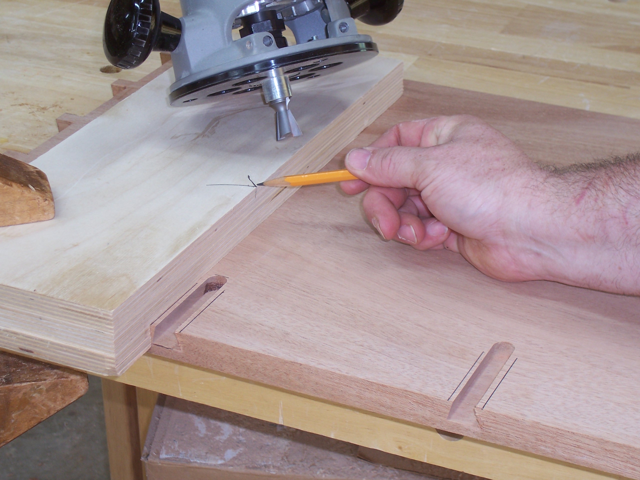
From the lathe the next step was to mortise the legs for the aprons, back and ends. While this work can be done while the leg is still as a blank, I think it’s better to actually see what the leg looks like before making a call as to where it will fit. After the legs are shaped, you can easily see which legs look best – those go to the front, while others move to the back. We had two mortisers setup and working, plus I demonstrated how to use a plunge router to do the work. Of the seven taking the class, only one used a plunge router for his mortises. (It’s great during classes to use tools you don’t have in your shop, as long as you know how to do the work when you’re at home.) One additional hint is to make sure that you’re cutting to the necessary depth – a couple of woodworkers had to make a return trip to the mortiser. Sorry I didn’t catch that sooner Mike.

IMG_1813
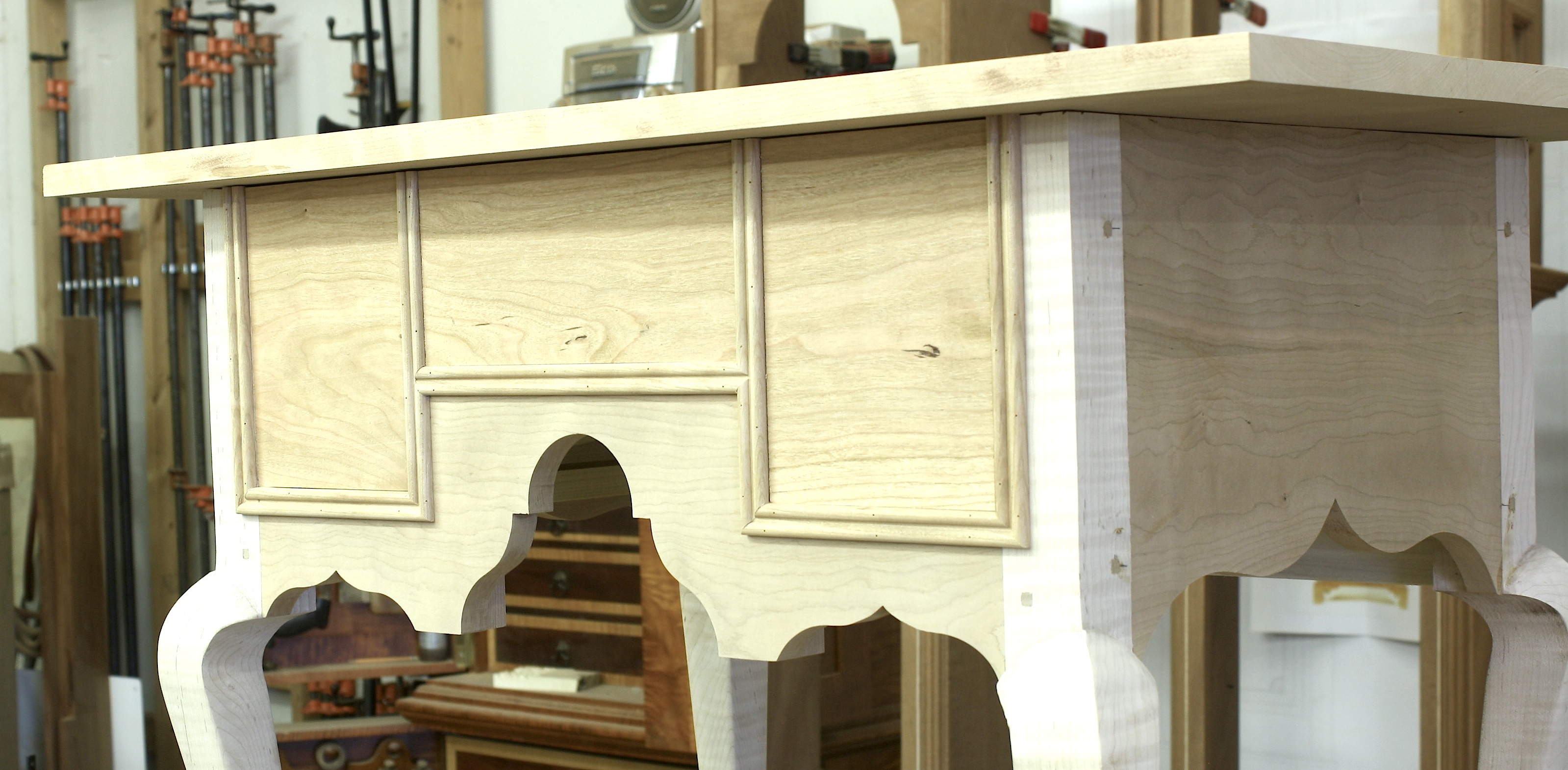
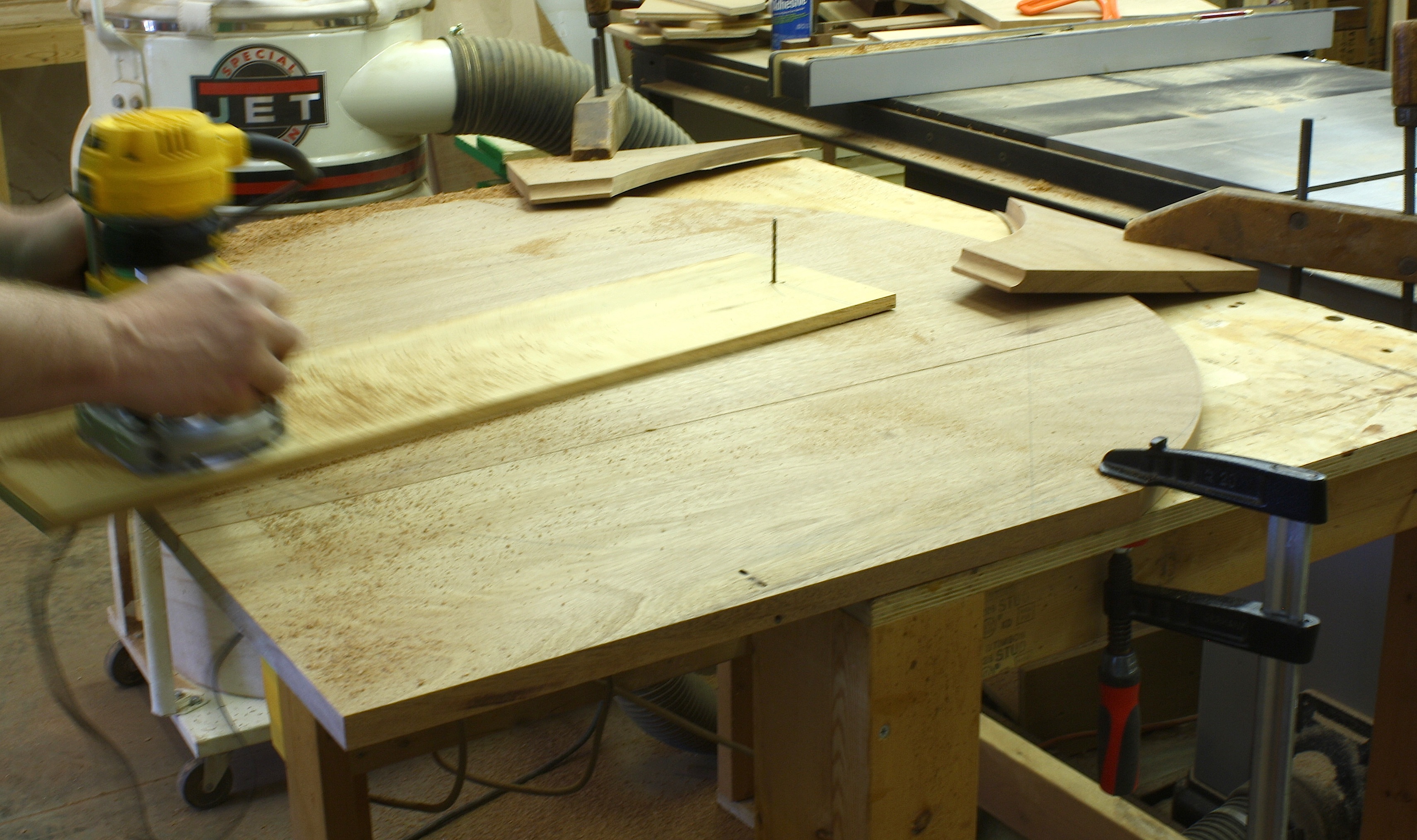
By Wednesday everyone had knocked out the remaining outside case pieces and the lowboys were beginning to take shape. Jon spent extra time on his legs – he also noticed the finer look of the lowboy at CHS. After cutting the designs for the ends and front apron, we worked on bending the cock bead. I was happy that the bends for the longer end-panel beads went so well. Most everyone got those pieces bent using a soaked piece of wood and a heat guy set on high – if you take your time, you can feel the wood give up as it melts into position. If you apply the heat for a bit longer, you actually set the bend just as if you left a steamed piece in the mold until it dried. Smaller, tighter pieces were made using a router with a specifically paired guide bushing and router bit. (Read the article to learn the setup.)

IMG_1820
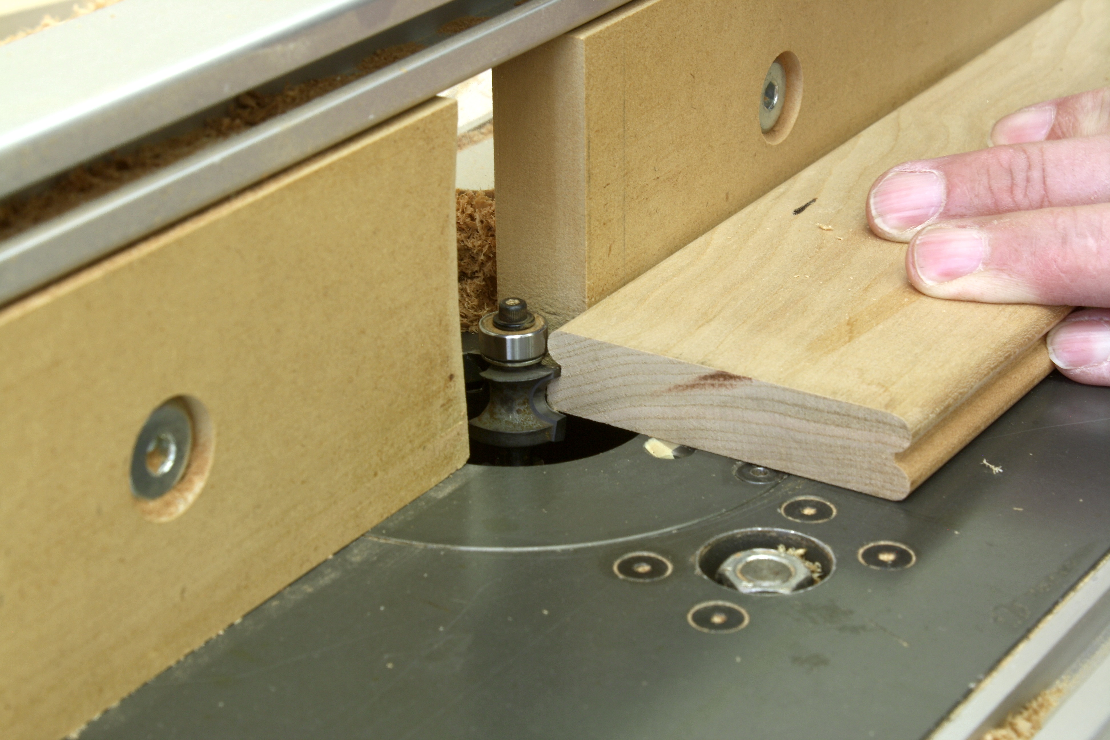
Work on the inside of the lowboy went smooth, aside from the occasional misplaced screw pocket. There were a couple of hand-cut dovetail sockets that needed attention, but overall the class breezed through the interiors. As the cases were coming along, the lowboy tops came into focus. A little router work was all that was needed. It took, however, two passes around the top to get the profile complete. And with this project, the profile continued on all four edges; I checked the original lowboy to make sure. Many tops from the period are molded only on three edges.

IMG_1825Late of Friday and most of Saturday, drawers were the topic at hand. Of the seven in the class, three decided to build the drawers with the slanted sides and back – a challenging task even if you’re experienced in dovetail work. As you may have guessed from the opening photo, not all the drawers were completed during the class. As it is with many classes, there is homework. Also, most of the class members decided not to glue up their lowboys. Flat-packing the pieces home is much easier than trying to cram a lowboy into the back seat.

The class went great. I worked with a lot of talented woodworkers. I’m amazed at how good many of the folks are who take classes. If they had more time in the shop, their work could easily rival many of the top woodworkers in the country. Take a class. It’s fun and it’s sure to improve your woodworking.

Build Something Great!

Glen


8 Comments

Filed under Uncategorized

Different Dovetailed Drawers

IMG_0622The drawers on the Connecticut lowboy that Bob Van Dyke and I found in the back room of the Connecticut Historical Society are tapered from bottom to top. I’ve mentioned in blogs (either here on my blog or on the Popular Woodworking Magazine (PWM) editor’s blog) that I’ve seen this treatment of drawers only one other place, and that was on Grove Wright’s Shaker work, including the Shaker Counter I copied and built in the June 2012 issue (#197) of Popular Woodworking Magazine.

The process of making these drawers is a bit different from regular hand-cut dovetailed drawers. To begin, the material for the drawers sides and back are tapered. Because there are two drawer depths on the one lowboy, there are two different tapers needed on the drawer parts. IMG_1280I set up my band saw to just leave the bottom of the parts uncut, and the top edge to cut leaving a 1/4″.

Off the band saw, the cut faces need to be smoothed. That could be a pass over the jointer. But with the narrow edge being only a 1/4″ in thickness, I think it was best to use a jointer plane. It’s from here that things get twisted. I used my marking gauges, but not in a way that is customary when dovetailing drawer parts. I set on gauge to 1/2″ and a second to 1/4″. I used the two gauges to place tick marks at the top (1/4″) and bottom (1/2″) to use as layout lines. IMG_1282The next step – where you would normally use a marking gauge – I used a straightedge and utility knife to score the baselines.

The trick to marking off the pins and tails is to use the square or outside face as a register. (If you use the inside face, your marks can be all kind of funky angles.) After the layout is complete, it’s a matter of sawing to the lines then chopping out the waste. Because I work pins first, I began with the pins in the drawer backs. To transfer the pins to my tail board, I set the completed back in position, making sure the orientation is correct. To cut the tails, I go back to the band saw and cut just off the layout lines, inside the pin waste area. Ordinarily, I would chop the waste at my bench, but because the parts are angled – and the waste area is so narrow – I stay at the band saw and trim the waste using power. Nibble. Nibble. Each time staying just tight to my baseline. Because this is a poplar-to-poplar fit, I get a little smash factor to make it all work.

IMG_1286The drawer fronts are not tapered, but the sides are. Again, I have to use the straightedge-and-utility-knife layout method, but from there the process is the same as with standard dovetailed drawers. The only difference is the tail sockets are tapered from top to bottom. To transfer my pins to the tail board (drawer sides), I set the front at my scribe lines, which is a consistent 1/2″, then transfer the lay out.

In the drawers of the Shaker Counter, the bottom was slid into the 1/2″ thickness of the bottom edge. The lowboy drawer bottoms at applied – it’s good to have the thickness at the bottom for nailing. I use the counter on a daily basis, and the drawers slide spectacularly. I’m wondering if it’s the design (heavy bottoms) or the yellow pine I used for drawer parts. I’ll have a better picture when the lowboy is wrapped up.

Build Something Great!

Glen

This lowboy is an upcoming project in Popular Woodworking Magazine. To see the entire project, pick up the February 2014 magazine – if you’re not a subscriber.

4 Comments

Filed under Antique Pieces, Joinery, Methods of Work, Shop Tips

To Scratch or Not

IMG_1276In a blended woodworking shop – how any woodworking shop should be set up – you make choices about when hand work is appropriate and when it makes better sense to use power tools. That decision should not necessarily be guided by a passion for any particular method or tool; as woodworkers, we face this whenever we hope to be productive in our shops.

In a post a few weeks back (read it here), I wrote about how easy it was to make a simple scratch beader (scratch stock) to profile the arched moldings on the Egerton clock hood. With that project on hold while I build a cover piece for an upcoming issue of Popular Woodworking Magazine, I faced a similar choice as I made drawer molding for the transitional lowboy. (If you’re a furniture purist, don’t tell me I’m not suppose to use the term transitional – that best describes the project on which I’m working.) IMG_1278The moldings are a double-bead design that signifies later William & Mary period work. And the fact that the lowboy has cabriole legs (Queen Anne) also indicates a transitional build.

I decided to make another simple beader, but this time the tool was a bit more involved. Not only did I drill the holes and sand the profile, I needed to set the blade into a handle to register the molding with each pass. Even with the handle added, making the tool was too easy.

In order to use the scratch beader, I ran a slot down the middle of my stock using a slot cutter setup in my router table. At the bench with the stock set in my vise, I scratched the double-bead profile into the edge. At my table saw, I set the cut for 1/4″ then ripped the first piece of molding free. Everything worked, but the process to get six pieces of molding was too long.

IMG_1270Using my router table with a 1/4″ corner-beading router bit installed, I ran a pass to form the bead, flipped the stock to rout a bead at the opposite face, then ripped the molding at my table saw. I was easily convinced that this was the process I would use. But what guided my decision? First there was the ease of the entire process. Router cut was far easier and quicker than walking through the steps needed to do the work by hand. Also, the pattern or profile was consistent with each piece of molding cut. This is important because there are a couple of places, as you can see in the opening photo, where these molding pieces meet and intersect with one another – matching profiles are easier to fit and blend (hand-cut work can require further shaping and sanding).

What did I give up? The original molding profile I was after was a 3/16″ bead at each edge of the 5/8″-wide stock, with a 1/4″ of flat between the two beads. What I made using power tools was a 1/4″ bead at both edges with an 1/8″ flat – not the same design. I could have found and purchased a 3/16″ corner-beading router bit, but I didn’t think it was that important. If this was a customer-purchased lowboy, I would have built the piece with the 3/16″ beads. But given the fact that it is a piece for me – as most of the projects you build are for you – I opted to be more productive in my shop.

Build Something Great!

Glen

3 Comments

Filed under Hand Tools, Jigs, Methods of Work, Power Tools, Routers

Oval by Geometry

Art_OpenerIn late 2010, I listened to furnituremaker Fred Roman talk about ovals and how to lay them out using geometry. I had always used a string method in the shop, and when I was in the home-building field, we used two framing squares. These days I use SketchUp.

The way he did it seemed point on and easy. The same way you could swing the arcs with a trammel, you could swing a router using a circle-cutting jig. I pushed for this to be an article (shown left) in Popular Woodworking Magazine(PWM). B_PlanA contract was executed and before the piece ran in the magazine pages, I had left to pursue other interests. Of course I read the article when it was published. The right-hand photo is the layout, but you should read the article to get the details. (PWM doesn’t sell the article as a stand alone, but you can pick up the August 2012 issue (#198) at shopwoodworking.com.)

I kept the method in mind for whenever it may be needed. That time arrived this weekend when Dave Griessmann was in the shop working on a Federal-period table. IMG_1187His top was ready to transform from a rectangle to an oval, so we pulled out Fred’s article to make it happen. Dave laid out the oval and was contemplating how to make the cut when I reminded him that he could swing the router to get the job done. He decided to router-cut the larger radii. The length of my often-used circle-cutting jig wasn’t long enough, so we substituted a length of plywood. At one end we drilled a 1″-diameter hole to match the outside radius of a guide bushing, at the other end we drilled a 3/16″ hole as a pivot. (We were working on the underside of the top.)

A couple of adjustments were made to the jig so we cut exactly at the layout lines, and so the jig could spin without any interference from the clamps used to hold the top. IMG_1189Everything was set and ready to go, so Dave powered up the router and made a light pass. The depth of cut was 3/4″ so we set up to make the entire cut in three steps, and he cut only half of the top. When we finished that half, the top was spun so the remaining half hung off the table and the step process was repeated. The cuts were perfect. In fact Dave wanted to setup and cut the ends the same way, but I persuaded him to cut those at the band saw and clean the edges using a disc sander. While he (and you) could do that, I think it’s much easier to trim the second radii so you don’t nick into the already cut edge. There’s no sense in taking the chance given the leaves of his table were easily cut at the band saw.

The entire process worked like a charm. I will use it over and over when I run into ovals – large ovals – in my work; small ovals are too easily cut using my band saw.

I included the photo below to show you the nifty clamping method we used to hold the arced edge for the second set of cuts. Our clamps could not reach the workpiece, so we lapped pieces onto the tabletop then clamped the scraps in place. This is a handy trick in a pinch.

Build Something Great!

Glen

IMG_1191

2 Comments

Filed under Jigs, Methods of Work, Routers, Shop Tips

Knee Surgery or Not

106If you build Queen Anne or Chippendale furniture, you most likely have made cabriole legs. If you’ve cut and finished cabriole legs, you most likely have work on knee blocks. Or have you? Over the years, I have run into three methods used to address knee blocks.There are knee blocks that fit in front of aprons, those that fit under aprons and there are cabriole legs that do not use blocks at all.

One habit I got into as I work on these curvy legs is to keep my cutoffs. The material you cut away from legs as you sculpt them from blanks perfectly matches the legs; the grain is right and the color is right. 110That’s the best material to use for your knee blocks.

In the opening photo you can see the first step in knee block fabrication. There are a few things to remember as you work on blocks. In the Massachusetts High Chest of Drawers DVD (the piece shown in the first two photos), the apron is behind the block. (You don’t, however, attach the blocks to the apron; they still attach to the legs.) As you make these leg add-ons, it’s important to match the grain. That can be difficult.

As you profile the knee blocks, each time you complete a step, the grain changes. When you make the cut to the pencil line in the photo, the grain moves. As you round the piece in the second step of the process, grain moves again. Dressing TableYou need to be able to read the grain as it appears in the finished blocks if you want to achieve the perfect appearance when you’ve completed the work. As you also see in the above photo, color matches are important – I didn’t do so good on that task.

Some blocks fit under the apron, as seen to the left in the cover project from the June 2010 issue of Popular Woodworking Magazine (#183). The importance of grain matching in this instance is the same. Even though the block fits under the apron, it still attaches to the leg and the grain should match. If the look and fit are correct, the connection appears seamless. That’s what you’re after.

This week I began building the Connecticut lowboy – and as always with me, I began with the legs. CT LowboyAnd I saved the cutoffs. As I got into the legs a bit farther, I realized that I didn’t need the extra material because these legs did not have knee blocks. What the maker did was round the material from the front of the knee to the inside edges. If you look at the legs straight on, you almost see a half circle as you view from the right side of the upper leg to the left side. It’s interesting when you first see it.

As you work the material to round the knee area, you also need to roll the material back toward the leg post. As I completed the shaping of the second leg, I realized that a #3, 20 carving gouge used inverted did a nice job rounding and rolling. (I used only my chisels sculpting the first leg.)

What struck me the hardest was that I was in the shop for about eight hours – probably worked for maybe five hours with all the talk and lunch – and two shaped legs was all that resulted. I could easily get all four legs complete a decade ago. I was reminded that my earlier shop was air-conditioned and working in the heat was most likely the cause for my lack of completion. Yeah. I’ll go with that. In my mind, though, I know it’s simply age.

Build Something Great!

Glen

Leave a comment

Filed under Back to Basics, Methods of Work

Make This Your First Lowboy

CT LowboyFor the past couple weeks, I’ve been working on SketchUp drawings for a Connecticut Lowboy discovered at the Connecticut Historical Society. The class happens at The Connecticut Valley School of Woodworking in September, immediately following the holiday weekend – the class runs from Tuesday through Saturday. (There are a few class spots left, so now would be a great time to contact Bob Van Dyke at the school to sign up.)

When I built The “Queen Anne Dressing Table” for the June 2010 cover of Popular Woodworking Magazine, I thought I had discovered the easiest-to-build lowboy ever. I was wrong. This project is easier, if you can believe that. And best of all, easy does not translate into ugly. IMG_0634In fact, when I wrote about my 2013 classes in January this year (read it here), I mentioned how this lowboy stopped both Van Dyke and me in our tracks.

What made the dressing table easy was that all the interior parts were nailed in place. What makes this piece easy is that there are few interior parts. Take a look at its inside. There is no top rail on the piece (the case top is the kicker to keep the drawers from tipping when extended), the two interior drawer dividers are solid pieces that run from front to back, drawer guides are nailed between the legs and the only runners are single pieces dovetailed into the front rail and centered in each opening.

Where a piece such as this picks up is pizazz is with details. One feature that makes this lowboy stand out is the cock-bead work at each of the cutouts in the front rail and at the sides. IMG_0623That work takes time to get right. But it adds a real punch to the finished piece. If you click to open the photo above, you can better see this detail. A second interesting detail, and one that makes me scratch my head and search for a connection, is the construction on the drawers. It’s not the fact that the bottoms are applied. That, along with the beaded moulding that wraps the drawer openings, indicates that this piece has an early origin. What I find interesting are the tapered drawer sides. This is nearly identical to the work found on the Shaker counter originally built by Grove Wright that I built for the June 2012 issue of Popular Woodworking Magazine. Is there a connection, or is this a construction method used in the region. Grove Wright spent time working at the Enfield, CT Shaker village.

IMG_0620

Above is another photo of the interior of the Connecticut lowboy. In this photo you can see a drawer divider. Check out how the divider is angled as it stretches from front to back. Was this a way to save on material? Also notice how oxidation affects the coloration on the divider. What you see is not two pieces of lumber with different colors joined together. It’s the fact that the upper section has, for more than a hundred years, been protected by the drawer with the lower section constantly exposed to the elements.

You really should take the time to join us at CVSW as we build a great looking, simply constructed and high in detail Connecticut Lowboy. Register here.

Build Something Great!

Glen


11 Comments

Filed under Antique Pieces, Joinery

GDH at WIA

This week, I want to mention Woodworking in America (WIA). With my return as managing editor with Popular Woodworking Magazine (PWM), you know that I’ll be and teach at WIA. If you are a woodworker in search of basic skills, you should plan to attend. If you are experienced at woodworking, but are looking to up your game, you should plan to attend. My bet is that if you look at the woodworkers PWM has presenting this year, you’ll want to be there, too. (Registration is open, so now is the time to make the call. Pull the trigger and click here to sign-up.)

This year my classes are all over the map. I open the conference teaching a seminar titled, “Better Woodworking Through Proper Wood Prep.” MIllingThe most basic observation I can give you is that if you begin a project with warped wood, you will fight it throughout the entire project. You need to make sure you know the basics, so of course we’ll cover the basics and you can bet there is way more. I’ve spent 20 years milling wood for projects. I’ve learned a crap-load of tricks and techniques to make the work easier and to mill lumber that is bent, twisted and just plain gnarly. In addition to the basics, I’ll share how to read your stock, what corner to press and when to straighten twisted stock, cup up or cup down and what to do if your board sticks at the jointer. This one class can make your time in the shop better.

Another class I’m teaching is “Precision Joinery: In a Hurry.” In this area alone, you discover why you need to be a blended woodworker. 9The class description from WIA says it best, “No single hand tool, power tool or machine is best to produce all the requisite joints. To make parts as quickly and accurately as possible, you need to know what tool to use when.” I’ve got jigs that make my life in the shop easy and highly productive, but I also know when to turn to my hand tools. During the class we’ll look at a number of furniture joints and I’ll share my best techniques.

On Sunday at WIA, I have a three hour class on inlay based around Federal-style inlay. Be sure to attend “Understanding Inlay: A Key Piece in Connoisseurship & Identification.” InlayIf you study inlay you’ll discover that each major city center had its own distinct inlay designs. One of the most famous (and often miscategorized) banding is the lunette inlay often associated with John and Thomas Seymour in Massachusetts. Every banding, inlay and patera is a clue to where the piece was built. Not only will we learn about different inlay and bandings, but I’ll demonstrate how many of these bandings are assembled. And before the class is over, you’ll be given the opportunity to make a sand-shaded fan that you can inlay into your project. So come ready to learn and ready to work, too.

Build Something Great!

Glen

Leave a comment

Filed under Inlay, Jigs, Joinery, Routers, Uncategorized