Monthly Archives: April 2014

Visit from the Highland Woodworker

C_BrockMost everyone looks forward to Friday, but this past Friday was especially fun. The Wednesday before was not so much fun – it was filled with wood dust, wood chips and  lumber stacking, but not in a good way. Wednesday evening I spent cleaning my shop and rearranging the tools for a visit from Charles Brock, the Highland Woodworker.

Chuck and his business partner Steve began their Friday at the American Woodworker and Popular Woodworking Magazine shop in Blue Ash, Ohio, filming clips for upcoming episodes of The Highland Woodworker, which is Web TV for Woodworkers. (If you aren’t familiar with Chuck’s online show, you should sit a spell and take in a few episodes when you have some free time.)

Screen CaptureLater in the afternoon, we drove to my shop where we filmed a short interview section in which I discuss some of my early woodworking adventures, talked about what I find relevant in woodworking and I even shared a couple of stories about my (and my Dad’s) early days with Popwood. From there we talked about jointers and jointer setup, and we spent a few minutes discussing aniline dyes in finishing – you have to make the tiger-maple curls “pop.”

All this film work will end up on The Highland Woodworker later in the year. And when I get an exact date, I’ll be sure to let you know. Until then, below is the current episode for you to watch. If you slide about 15 minutes into the episode, you’ll find a guy who looks a lot like me talking to Chuck about shellac, but do watch the rest of the show. There’s some great woodworking information to be found, and best of all, it’s entertaining, too.

Build Something Great!

Glen

1 Comment

Filed under Uncategorized, Video

One Becomes Three

Photo courtesy of H. L. Chalfant Antiques in Wets Chester, PA

Photo courtesy of H. L. Chalfant Antiques in Wets Chester, PA

When talking about antique chest of drawers, “chest speak” often mentions drawer layout to describe a piece. You’ll read in a magazine advertisement, in an auction catalog or on a web site that it’s a three-over-five design, or a two-over-three-over four design. What is being described is the number of drawers stacked over the next bank of drawers. The first example would be three drawers set in the top row with five full-width drawers set below. The second example would have two drawer in the top row, and three drawers that make up the second row, with four full-width drawers stacked below. (The top rows are often reversed as shown in the opening photo.) Combinations are endless, but you don’t often see numbers get out of hand.

There is something to keep in mind as you look at drawer layout. Is the bank of drawers actually divided into two or three drawers, or is that a single-width drawer made to look like it’s divided? If it’s a single drawer made to look like three, what’s an easy way to duplicate that if you were building the chest? One way is to use an ovolo router bit.

An ovolo bit is similar to a roundover router bit, but there is nothing attached IMG_1599to the bit to guide it path – no pilot (that’s a throw-back design) or bearing such as what we have on most roundover bits. In the right-hand photo you can see the difference between the two different bits that basically cut the same profiles. Both router bits shown have a 1/4″ roundover profile. (Click the photo to enlarge the image.)

The way to use an ovolo bit is to first profile the edge of your drawer front using a roundover bit. Next, chuck the ovolo bit into your router, set the depth of cut to match the roundover profile, clamp a straightedge to the workpiece and run test cut. Measure the distance from your straightedge to the exact center of your ovolo profile. You’ll need that as you layout for the cut in your drawer front. (With my ovolo bit the width of the completed profile is 1″.) Layout work can be tricky. If you don’t pay attention, it’s easy to get the faux fronts a bit off in width.

IMG_1602

Once the layout work is done, measure from the layout line to where you need to set your straightedge, clamp it in position and you’re ready to divide your drawer front. Work slow as you rout, it’s easy to flip out the profile as the router bit enters the cut.

How can you tell the drawer front is not really three individual drawers? Look closely at the vertical divider areas. You’ll see a small gap at the top of each divider if the drawer front is a single-width front and the furnituremaker was attempting to fool your eye.

Build Something Great!

Glen


Leave a comment

Filed under Antique Pieces, Design, Power Tools, Routers

3 Accepted Foot-to-Case Connections

Last week, after I professed that everyone should have a spindle sander, A few readers asked how I used a spindle sander as a thickness sander. It turns out that I have posted that technique, but it was inside another post. Here’s a link to that post; you’ll find the spindle sander being used to thin ebony string about halfway down the post.

Entertainment_Center copyOn to the next topic: How to attach feet to your case. Of course, there are a few ways to get feet on your cases. There are three methods I generally use on most every case. The first is to attach the feet directly to the bottom of the case, a second method is to rout the top edge of the joined feet and install a plate through which screws affix the assembled unit to the case bottom and the third method is to attach feet to a frame then attach the frame to the case and use a transition molding to cover the through dovetails where the case bottom joins the sides. I mention other methods, because I’ve built a couple of chest – full-size and spice boxes – from Chester County where the feet were attached directly to stiles of the frame and panels sides. While this is not commonplace, it, along with other methods, is sometimes done.

To attach feet directly to the case, I begin by installing a molding to which the feet are glued. You wouldn’t think that you could assemble feet to a molding and that would be strong enough to hold everything for 200 years. IMG_1590Of course, you would be correct. What really holds the feet to the case are  glue blocks. These blocks also carry the bulk of the load of your chest. On the case I’m currently at work on, the thickness of the feet allows about an 1/8″ of the feet to lap onto the case itself. Then, with the glue blocks in place, the weight of the case is divided on the actual feet and on the glue blocks – the vertical block holds the weigh while the two horizontal blocks keep the assembled foot attached.

The next method is a bit more work. And the added plate makes the connection easier, but not necessarily any stronger. After the two foot pieces are joined via miters, I rout a small lip on the inside of the feet using a rabbeting router bit to which I attach a thin plate. Plate
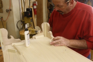
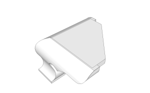
The SketchUp drawing at the left shows how the plate fits to the feet; a thin bead of glue and brads secure the plate to the feet. The assembled unit is then screwed directly to the case bottom with the unit sticking out in front of the case. The look is completed by wrapping a molding around the case. An example of this type of connection is seen in the opening photo, although you cannot see the plate. That’s by design. As you see in the drawing, the cutout for the plate does not blow through the end of the foot.

The last method – the option that I find the most used as I look back at furniture I’ve built throughout the years – is to attach the feet to a base frame which is then attached to the case. Foot&Frame3I used this method on the Pennsylvania blanket chests in the August 2009 issue of Popular Woodworking Magazine (#177) and the Serpentine chest from issue #195 (February 2012). As you can see in the right-hand photo, the same idea of glue blocks is used – mainly for reinforcement in this case. The frame is attached to the front of the chest with screws, but the remaining frame is nailed to the case bottom to allow for seasonal adjustments. The look is then completed with a transition molding.

These are three good methods used to attach feet to cases. There are pros and cons to each, as there is with any technique used in woodworking. Whenever you here, “This is the only way to do it,  run in the opposite direction. You have choices.

Build Something Great!

Glen


3 Comments

Filed under Joinery, Methods of Work

Shop Shortcuts – Foot Pattern

I do a lot of work with patterns. Most often, my patterns are used to guide a router bit (top-mounted bearing) to finalize a profile. But the pattern shown here is used only for layout.

IMG_1578When building any chest of drawers that has bracket or ogee bracket feet, I make a pattern for the foot. I use six individual feet for the show sides of most chests, with the two rear feet being a more plain design and usually made out of secondary woods. To make my fancy feet, I could simply use a paper pattern to layout the design, but my pattern would be in shambles as I worked on the sixth foot. Another option would be to print six copies of the design then glue each paper to a foot blank before going to the band saw to cut out the designs. I, however, make a pattern using scrap 1/4″ plywood which holds up to not only the six uses on this chest, but will be around the shop if I make a second or third chest, and will be standing at the ready for a completely different future chest if the design was right.

IMG_1573Here’s the process in case you’re not yet a pattern maker. I pull a paper pattern out of my SketchUp drawing (you could, of course, lay out the foot using pencil, compass and straightedge), cut it out then stick it to the plywood with spray adhesive. Then it’s off to the band saw to trim to the lines. Be close, but don’t hit the lines. And more important, don’t cut away the circle at the center of the foot that helps form the spur. We need that area later in the process.

IMG_1575After working at my band saw, my next step is at the spindle sander. After you have the correct spindle installed, work to your layout lines. Again, leave the lines intact. If you don’t have a spindle sander (see below), you can file and rasp your way to a great design.

Why would you not have an inexpensive spindle sander in your shop? Even the cheap machines last forever – I still have a Ryobi spindle sander from 15 years ago that I take to classes and seminars if need be. And there’s a lot that you can do with these simple machines, including thickness-sanding inlay and veneer.

IMG_1577The last step to prepare the foot pattern for work is to find and create the center point of the waste area the forms the spur. On all my feet, this waste to drilled out using a Forstner bit at my drill press. To find the center point, position the pattern under your drill bit until the circle is perfectly centered, then plunge down to leave a mark. I then drill down about a 1/16″ to set the waste area and just puncture through the pattern. The last step before putting this shop-made template to work is to completely pierce the plywood with a small drill bit.

The opening photo shows how the pattern is used. I’ll add a word of caution here. If you’re foot stock is a bit less than desirable on the rear face, make sure you flip the pattern as you work – lay out three feet facing left and three facing right. That way you can produce pairs that all show the correct face forward. And this is something you have to do if you’re using these patterns for ogee-bracket feet.

Build Something Great!

Glen


6 Comments

Filed under Jigs, Methods of Work, Shop Tips