Monthly Archives: September 2013

To Scratch or Not

IMG_1276In a blended woodworking shop – how any woodworking shop should be set up – you make choices about when hand work is appropriate and when it makes better sense to use power tools. That decision should not necessarily be guided by a passion for any particular method or tool; as woodworkers, we face this whenever we hope to be productive in our shops.

In a post a few weeks back (read it here), I wrote about how easy it was to make a simple scratch beader (scratch stock) to profile the arched moldings on the Egerton clock hood. With that project on hold while I build a cover piece for an upcoming issue of Popular Woodworking Magazine, I faced a similar choice as I made drawer molding for the transitional lowboy. (If you’re a furniture purist, don’t tell me I’m not suppose to use the term transitional – that best describes the project on which I’m working.) IMG_1278The moldings are a double-bead design that signifies later William & Mary period work. And the fact that the lowboy has cabriole legs (Queen Anne) also indicates a transitional build.

I decided to make another simple beader, but this time the tool was a bit more involved. Not only did I drill the holes and sand the profile, I needed to set the blade into a handle to register the molding with each pass. Even with the handle added, making the tool was too easy.

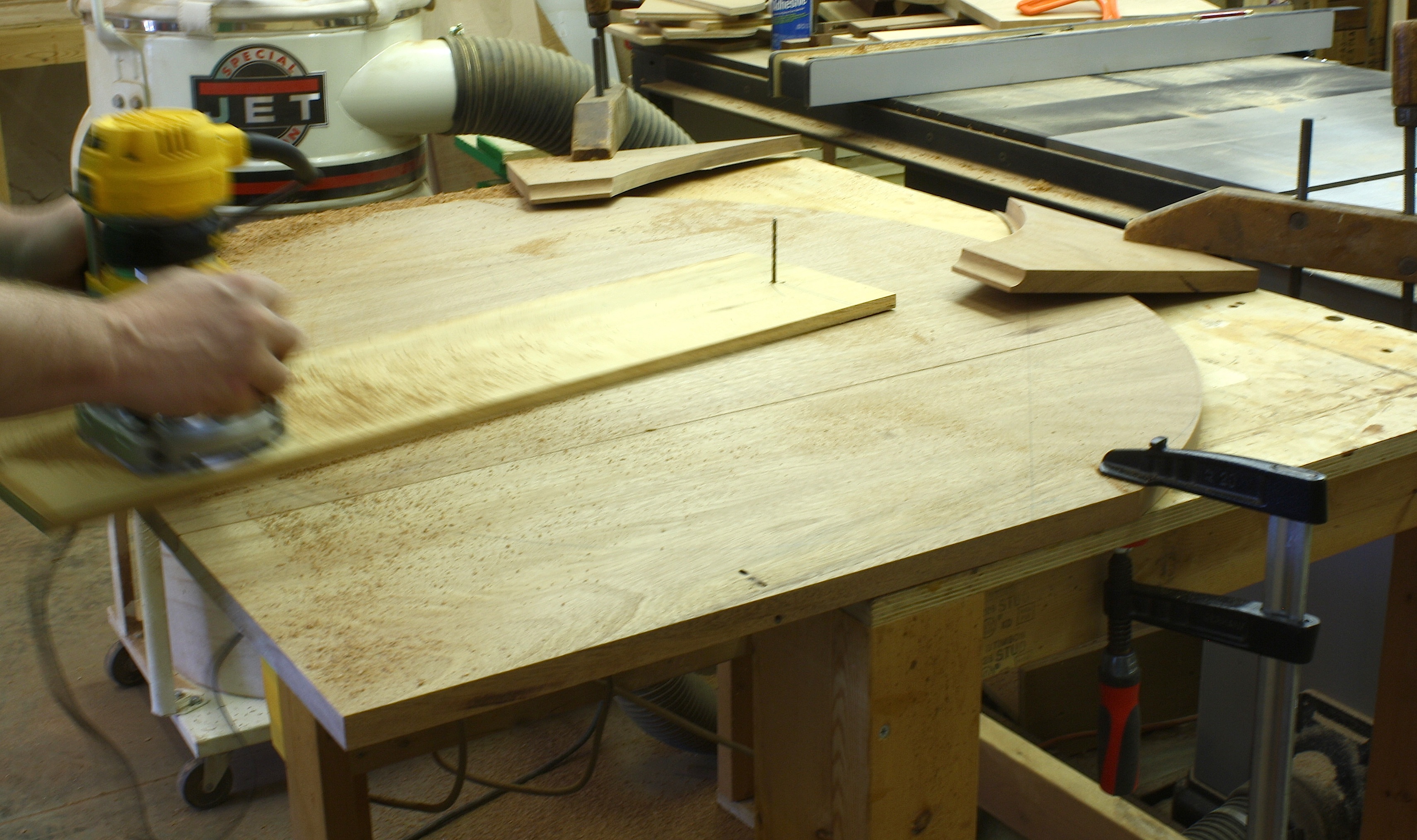
In order to use the scratch beader, I ran a slot down the middle of my stock using a slot cutter setup in my router table. At the bench with the stock set in my vise, I scratched the double-bead profile into the edge. At my table saw, I set the cut for 1/4″ then ripped the first piece of molding free. Everything worked, but the process to get six pieces of molding was too long.

IMG_1270
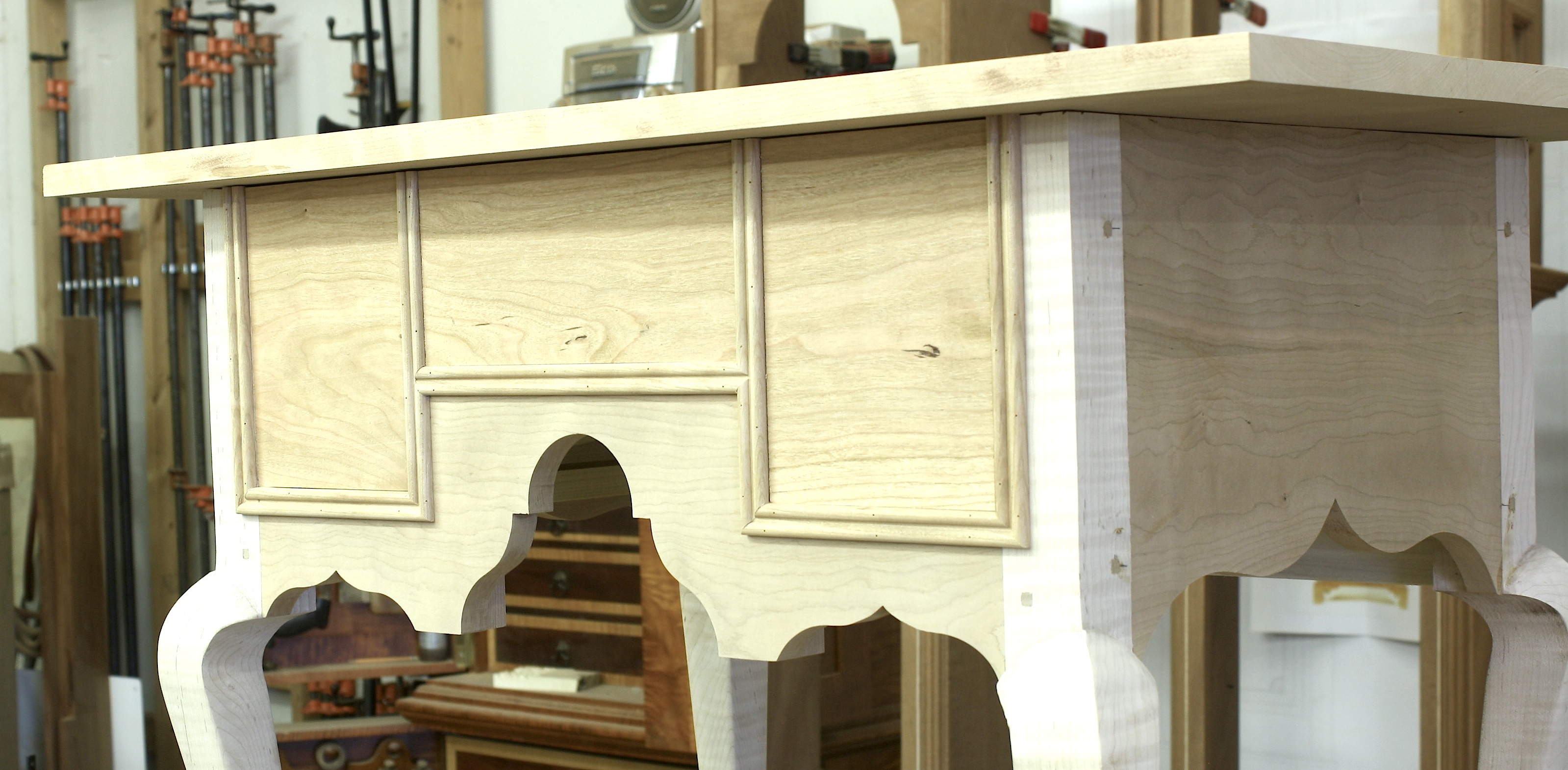
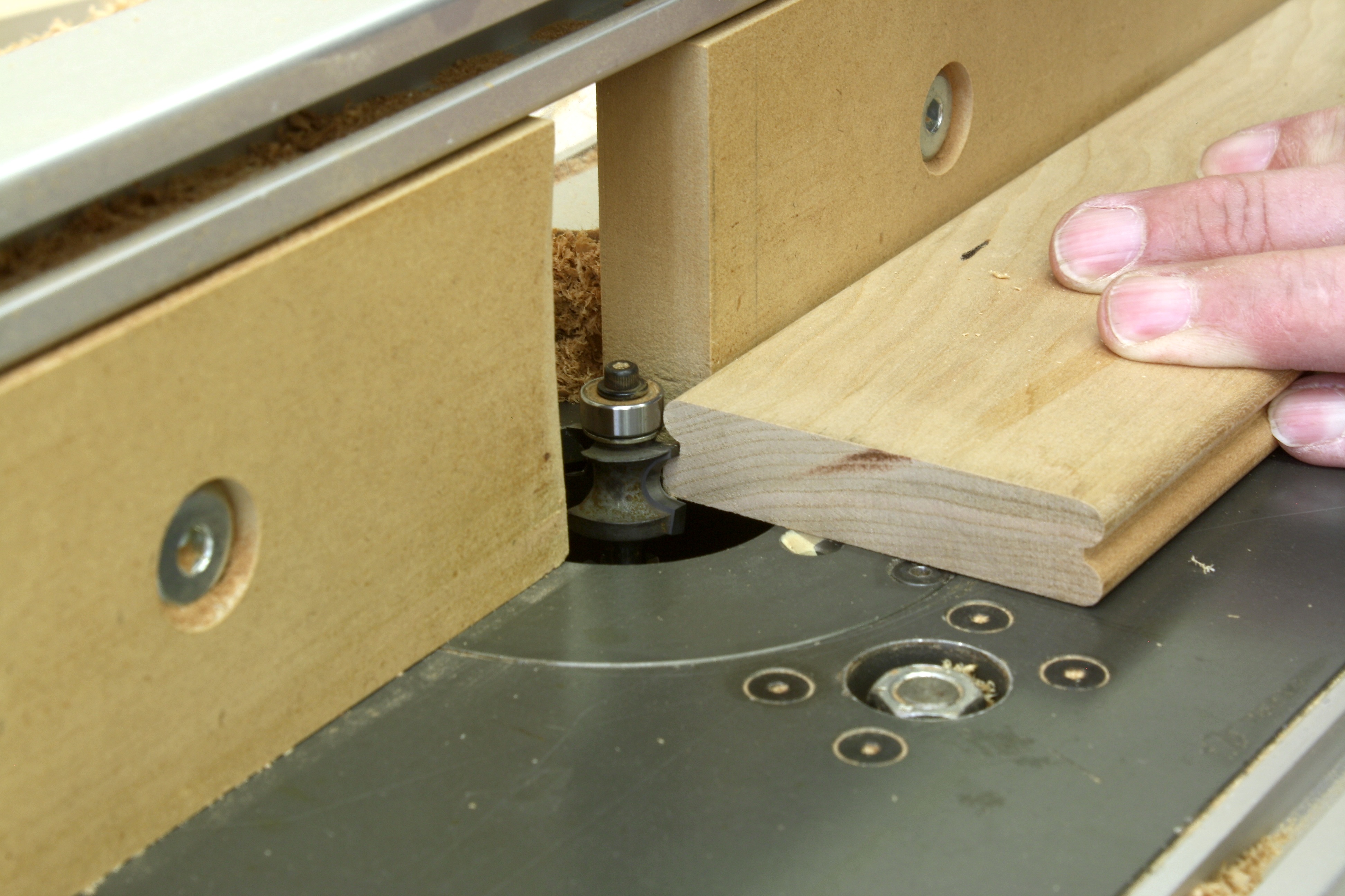
Using my router table with a 1/4″ corner-beading router bit installed, I ran a pass to form the bead, flipped the stock to rout a bead at the opposite face, then ripped the molding at my table saw. I was easily convinced that this was the process I would use. But what guided my decision? First there was the ease of the entire process. Router cut was far easier and quicker than walking through the steps needed to do the work by hand. Also, the pattern or profile was consistent with each piece of molding cut. This is important because there are a couple of places, as you can see in the opening photo, where these molding pieces meet and intersect with one another – matching profiles are easier to fit and blend (hand-cut work can require further shaping and sanding).

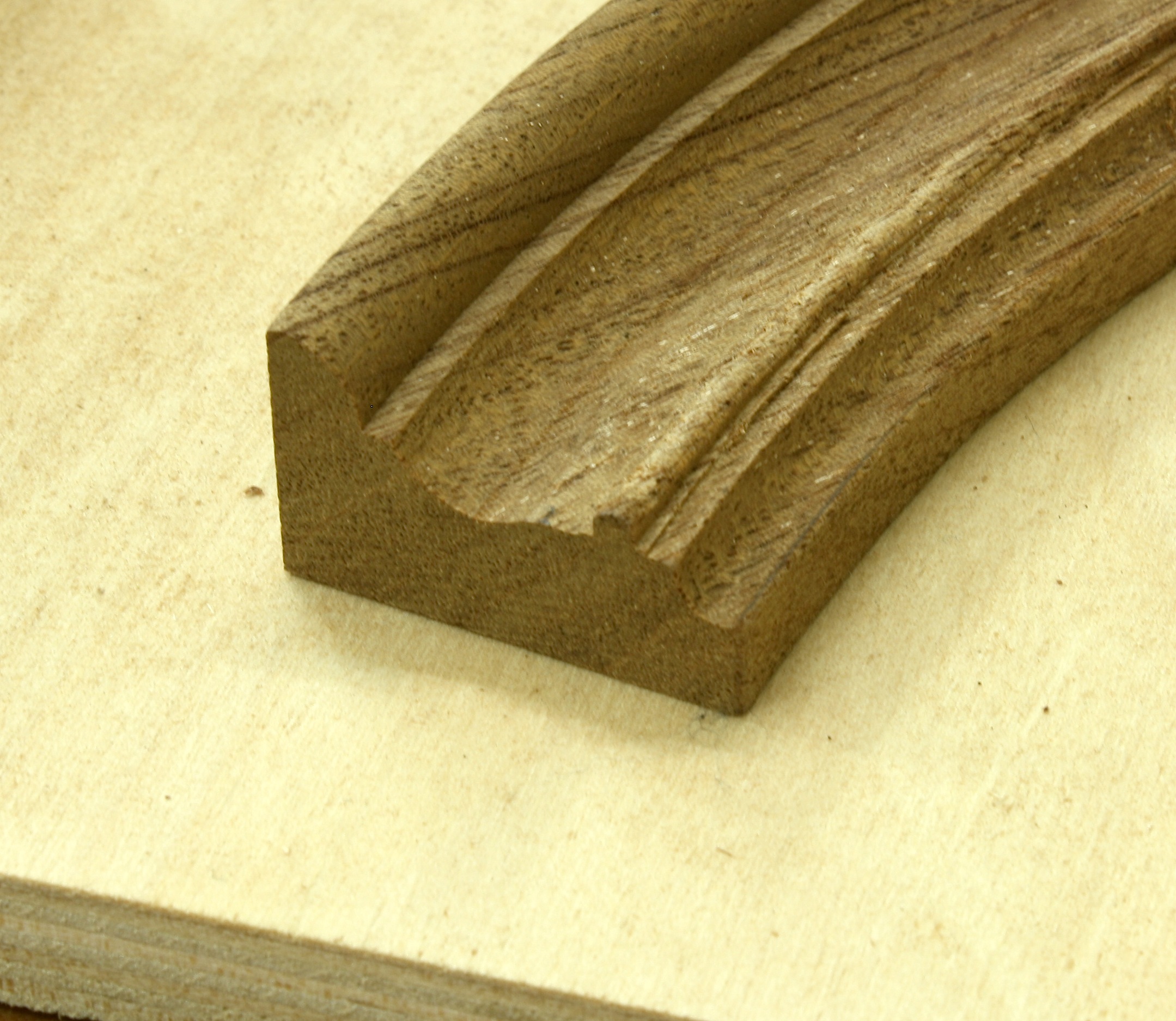
What did I give up? The original molding profile I was after was a 3/16″ bead at each edge of the 5/8″-wide stock, with a 1/4″ of flat between the two beads. What I made using power tools was a 1/4″ bead at both edges with an 1/8″ flat – not the same design. I could have found and purchased a 3/16″ corner-beading router bit, but I didn’t think it was that important. If this was a customer-purchased lowboy, I would have built the piece with the 3/16″ beads. But given the fact that it is a piece for me – as most of the projects you build are for you – I opted to be more productive in my shop.

Build Something Great!

Glen

3 Comments

Filed under Hand Tools, Jigs, Methods of Work, Power Tools, Routers

Screw Gains

“Their usual solution was a pair of large screws driven forward through the side rail into the front leg to supplement the hidden mortise-and-tenon joint. Each screw fits into a drilled and carved out ‘pocket’ or ‘screw gain’.”

IMG_1248Immediately as I mention pocket screws, many woodworkers’ eyes roll back into the heads as if this method of joinery is totally unacceptable. Of course, there are places where the use of pocket screws is not the best choice. There are also places in woodworking where the joint is the perfect solution. It’s up to us to know the difference and where to draw the line.

But the more you discover about pocket screws, the more fuzzy the line becomes. I’ve been in million-dollar homes, standing in kitchens that easily cost six figures, and the face frames on the cabinets were pocket screwed. Perfectly acceptable? You betcha. But that’s not furniture, right? No it’s not, but the quote above is about furniture. It’s about great furniture. Museum-quality stuff. The quote is taken from the book by Robert D. Mussey Jr. titled, “The Furniture Masterworks of John & Thomas Seymour.” The Father and son team used pocket screws. This method of joinery is not a new concept conjured up by the Kreg company, but it has elevated pocket screws to a whole new level.

The reason I write about pocket screws this morning is that I have a decision to make on the lowboy I’m building based on the piece found at the Connecticut Historical Society.

IMG_0636The lowboy has no front rail at the top of the case – the drawers kick right up against the underside of the top. There is no room for wooden clips, and I hate “figure eight” fasteners. Therefore, to attach the top I need to be creative. Or not. The top on the original was nailed or pegged to the case. I’ve seen a number of antiques that have tops nailed in place, so it’s not out of the ordinary to do so. The problem I have is that at one of the pegs – it looks like a round dowel – the top has cracked. I’m not looking to repeat that problem, but I do need a secure top.

In one of the photos I have of the original, you can see a metal angle used to gain a hold. I don’t think that is how the piece was built, but a later addition. Not what I’m after. As a result, I’m turning to pocket screws. And while I have respect for the Kreg joinery setup, I’m looking for something more traditional.

Yesterday I scanned the above-mentioned book to find ideas. I had it in my head that most pocket screws holes in antique furniture were basically v-shaped cuts, then I re-discovered the Seymour pockets. Their pockets were rounded, tapered and neatly shaped. I had something to work toward.

IMG_1252My first attempt was using a carving gouge. I used a 9/20 fish-tail gouge to carve out a pocket (see the opening photo). It looked good, but was work heavy. As I studied the shape and design, I remembered a simple jig that I had built years and years back for use with my drill press, so I dug it out, dusted it off and made it work with a newer press. (On my older DP, the jig slipped over the table, but now I had to clamp the unit in place.)

The jig is built with its fence tilted back at a 22.5-degree angle. To align the workpiece, I position it at the intersection of the jig’s fence and base as it stands on an edge. The DP head and jig are arranged until the workpiece stands under the 1″-diameter drill bit so the back edge of the bit is even with the back face of the workpiece. Clamp everything secure. I then lay the piece back tight to the fence and add a couple of spring clamps as needed. To cut the rounded, tapered hole, drill as you normally do. (Play with the bit diameter and thickness of your workpiece to find the best results.)

Below is a test piece I made using all three methods. Each of the different pockets are aligned with the tools used to make those pockets. Which am I going to use? Easy. If you read the quote above, it states that the “screw gains” (fancy-speak for pocket holes) were drilled and carved. I plan to drill the bulk of the waste using the jig and drill press, then clean the gains with my carving gouge.

IMG_1251

Which method would you use?

Build Something Great!

Glen

11 Comments

Filed under Jigs, Joinery, Shop Tool

Oval by Geometry

Art_OpenerIn late 2010, I listened to furnituremaker Fred Roman talk about ovals and how to lay them out using geometry. I had always used a string method in the shop, and when I was in the home-building field, we used two framing squares. These days I use SketchUp.

The way he did it seemed point on and easy. The same way you could swing the arcs with a trammel, you could swing a router using a circle-cutting jig. I pushed for this to be an article (shown left) in Popular Woodworking Magazine(PWM). B_PlanA contract was executed and before the piece ran in the magazine pages, I had left to pursue other interests. Of course I read the article when it was published. The right-hand photo is the layout, but you should read the article to get the details. (PWM doesn’t sell the article as a stand alone, but you can pick up the August 2012 issue (#198) at shopwoodworking.com.)

I kept the method in mind for whenever it may be needed. That time arrived this weekend when Dave Griessmann was in the shop working on a Federal-period table. IMG_1187His top was ready to transform from a rectangle to an oval, so we pulled out Fred’s article to make it happen. Dave laid out the oval and was contemplating how to make the cut when I reminded him that he could swing the router to get the job done. He decided to router-cut the larger radii. The length of my often-used circle-cutting jig wasn’t long enough, so we substituted a length of plywood. At one end we drilled a 1″-diameter hole to match the outside radius of a guide bushing, at the other end we drilled a 3/16″ hole as a pivot. (We were working on the underside of the top.)

A couple of adjustments were made to the jig so we cut exactly at the layout lines, and so the jig could spin without any interference from the clamps used to hold the top. IMG_1189Everything was set and ready to go, so Dave powered up the router and made a light pass. The depth of cut was 3/4″ so we set up to make the entire cut in three steps, and he cut only half of the top. When we finished that half, the top was spun so the remaining half hung off the table and the step process was repeated. The cuts were perfect. In fact Dave wanted to setup and cut the ends the same way, but I persuaded him to cut those at the band saw and clean the edges using a disc sander. While he (and you) could do that, I think it’s much easier to trim the second radii so you don’t nick into the already cut edge. There’s no sense in taking the chance given the leaves of his table were easily cut at the band saw.

The entire process worked like a charm. I will use it over and over when I run into ovals – large ovals – in my work; small ovals are too easily cut using my band saw.

I included the photo below to show you the nifty clamping method we used to hold the arced edge for the second set of cuts. Our clamps could not reach the workpiece, so we lapped pieces onto the tabletop then clamped the scraps in place. This is a handy trick in a pinch.

Build Something Great!

Glen

IMG_1191

2 Comments

Filed under Jigs, Methods of Work, Routers, Shop Tips

My Night Cap

#5024-01There are times when I need to get into the shop just to have fun. That time generally rejuvenates me so I can get back to my projects with a renewed vigor. If that fun time also happens to be something I need for one of my projects, I consider that a bonus. This week was a bonus. I needed to make a piece of inlay for the tall clocks. In the photo you can see, on the original Egerton clock, the piece of inlay I needed to make, the Night Cap perched on the post. This post is more pictorial that text filled, but you know what is said about a photo.

Step one was to develop a pattern for the inlay. I could have drawn the design free-hand, but it’s easier to pull the image into SketchUp and trace over the lines. After I had the plan, I spray-glued the images onto a piece of scrap holly and cut the pieces at my band saw.

B_IMG_1152

When I had the pieces cut out, I smoothed the edges as best I could using a disc sander and fine rasp before moving on. I also made sure the two pieces fit together nicely. I wasn’t worried about a super-tight fit because the separation would better show the delineation between the two pieces.

C_IMG_1154

Using a bench hook, I sawed the pieces into thin, usable slices. I like my Japanese saw for this cut. It’s thinner kerf saves material, and the small, finer teeth make the task easier.

D_IMG_1155

Sand-shading is great. There are few techniques as simple as this. And the results add a crap-load to the overall look of your work. The only pieces in this design that get shading are the small ovals.

F_IMG_1160

To inlay the pieces into my stock, I have to excavate the waste. This is really where a router becomes valuable. I positioned the pieces to my backer, then carefully traced around each piece with a sharp pencil. With a 1/16″ straight bit loaded into the tool, I set the depth of cut then hogged out as close to the lines as possible.

G_IMG_1163

Afterward, I used a small carving gouge to tweak the inlay area to my layout lines. I tested the fit of my inlay to the excavated hole, then trimmed any needed spots. (I want a tight fit, but not so tight as to break my inlay.)

H_IMG_1161

With the areas cut away and trimmed to an exacting fit, I added glue into the recess and hammered the inlay pieces into place.

I_IMG_1162

The rod for the Night Cap holder couldn’t be easier. I used the same 1/16″-diameter bit, set the workpiece flush with the edge of my bench then used a guide fence on the router to cut the line. The rounded ends from the router bit worked great against the small ovals to complete the design. A piece of string was cut to fit, a small amount of glue was injected then I hammered into the recess.

J_IMG_1164

At my table saw, I set the fence and raised the blade to trim the edges for more string banding. The pieces were cut to size and I mitered the corners using the reflection in the back of my chisel to set the angle – too easy. Glue to hold and blue tape as a clamp, then let it dry.

K_IMG_1165

With the glue dry, I sanded each face – I built two of the pieces – then cleaned up the edges with my block plane. Before I install these on the clock hood, I’ll thin the assembly somewhat. The two pieces are a bit different. So, are the results perfect? No way, I wouldn’t expect that. Was it fun to do? Hell yes. Every once in  while you need to get into the shop to just have fun.

A_IMG_1182

Build Something Great!

Glen

7 Comments

Filed under Design, Hand Tools, Inlay, Methods of Work, Power Tools, Routers, Shop Tips, Tall Clock

… Just Scratch It

IMG_1141Last week I worked on the arched moldings for my clock and left you with going back into the shop to used different setups and a new design. It worked. Kind of. It turns out that I did use my Micro Fence circle-cutting jig, but I had to also use my shop-made jig, too. The Micro Fence system did not allow me to get as small as I needed to make my moldings. The opening photo is that of the second profile as it came off the router. (You can enlarge the photos if you click on them.)

This week I began from the profiled arched moldings.IMG_1144 Three things to do: cut the arched pieces from the stock, make a set of straight moldings to match what I had in the arched set and work the small bead of the moldings. At the band saw, I cut away the waste to free the almost completed arched moldings. A quick trip to my disc sander (the outside edge) and my spindle sander for the inside edge and I was ready to begin matching the profile on some straight stock.

One of the ends of each of my four arched moldings is square cut – IMG_1147the ends that met in the middle of my setup. Using that end, I worked through the profile using the same router bits used to make the arched pieces. I had to set the depth of cut and the fence location to accurately match the design. It took about two hours to create a matching design on my straight stock. The last cut was the 1/4″ round-nose bit profile. With its work complete, I could rip the molding pieces free.

The last step was to create the 1/8″ bead on each of the sticks of molding. IMG_1150My first thought was to carve the pieces. I grabbed a small, bent-back carving gouge from the roll and got ready. After a couple minutes, I knew this was not the answer. Plan B – which should have been Plan A in retrospect – was to make a scraper for the task. Simple enough. I drilled an 1/8″ hole near the edge of one of my scraper blades, then ground it (sanded it with my spindle sander) so only half the profile showed. Work began on a straight piece of stock. Scrape. Scrape. Scrape. Done. It was too easy. The second, third and fourth pieces of straight molding went just as quick. But what about the arched pieces? I clamped one in my vise and went at it. The results were just as great and just as quick. The finished molding is shown above right, and the process is shown below. (The inset photo is the bead scraper.)

Combined

If you run into this need, make a scratch beader your Plan A. It’s way easy to do. And it works.

Build Something Great!

Glen

1 Comment

Filed under Hand Tools, Methods of Work, Shop Tips, Tall Clock