The Egerton tall clock I’m working on has two small oval inlays set into the waist-section face frame, so this is a perfect time to discuss and evaluate ovals.
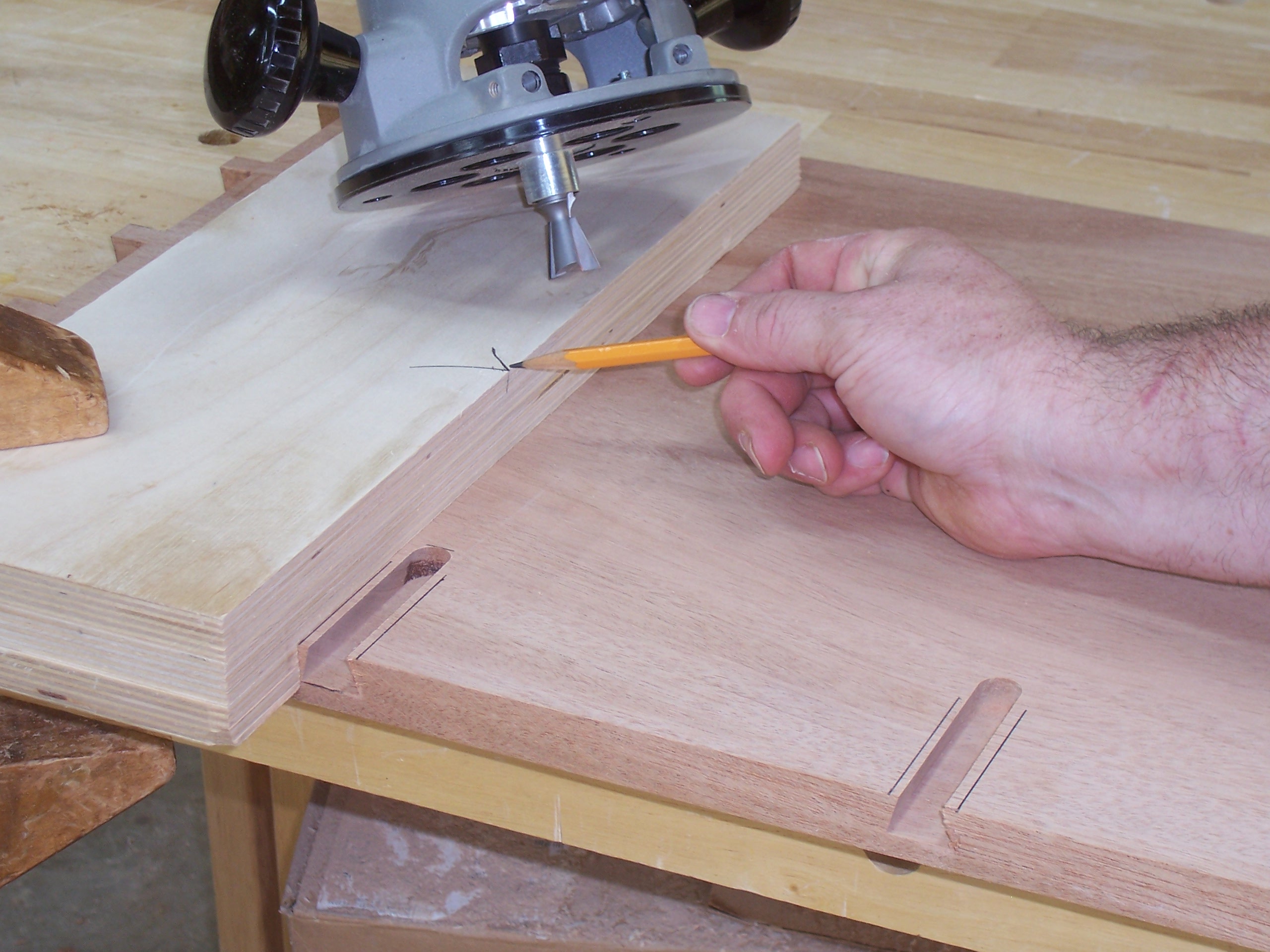
In the period, channels for inlay were scratched into the surface using a compass, or something similar tool. Today we can work with a variety of tools, both hand and powered, to plow our grooves – hand work with a compass or inlay tools available from LeeValley & Veritas or Lie-Nielsen, and, of course, a router if you wish to power-up the process. But before you actually get to that step, you have to design your oval.
For me, ovals have been pulled from some type of computer drawing program, such as SketchUp. In the August 2012 issue of Popular Woodworking Magazine, Freddy Roman (periodcraftsman.com) wrote an article about the ellipse. More to the point, about false ellipses. What is the difference and why should you choose one method over the other? Here is my take on this. If you plan to scratch in your oval pattern, or to use a router attached to a trammel to swing an oval, You better understand and use false ellipses. If, on the other hand, you plan to make a pattern to guide your router setup, any old ellipse will do.
Which technique do I choose? That’s not as easily answered as you may think. Because I have my clock waist assembled just as shown in the opening drawing, I would be unable to scratch my ovals into position – in order to draw the flat arcs necessary to create the long sides of my ovals require that I set my compass point more than 5″ from the center of my oval and that area is not available. That, however, does not keep me from using Freddy’s method to develop my pattern which would guide my router. Another option would be to create a piece of veneer with the string inlay in place, then glue that veneer to my clock.

Let’s begin with a comparison of the two ovals. Above you can see a distinct difference in the two drawing methods. A false ellipse, shown on the left, has ends that are more rounded because a compass or inlay tool works on a radius. The oval on the right is drawn in SketchUp. It’s ends are more pointed and could not be grooved using hand tools alone.
I will refer you to Freddy’s article for the steps necessary to produce a false ellipse. (I worked through the layout for my ovals.) Here, I’ll share how I use SketchUp and Preview (a MAC program) to produce an oval. (Before MAC, I worked in Microsoft Publisher for similar results.)

The first step is to layout the perimeter of the oval you wish to draw, then use the Circle tool centered at the middle of your proposed finished oval. Pull the radius out to the long end of your oval – here that is the top and bottom of the oval.

Next, use the Scale tool to pull in one side of your oval. Repeat the step to pull in the second side, as well.

The last step in SketchUp is to export your drawing. (This process is shown with the drop-down menu.) The image is saved in a file on your computer.

Open your file in Preview or another similar program, then set the parameters to crop the image touching all four sides as shown.

Under the Tools menu in Preview, select “Adjust Size”, enter in your required size then click OK. (Note that the size shown is not the actual size I needed for my clock.)

After the size is established, click print. As the menu to print opens, you’ll notice there is an option that allows you to print to scale. Set the scale at 100 percent before you print.
You now should have an oval that fits to your required layout size. I take that print-out into my shop, cut it free then transfer the pattern to a piece of plywood to use with my router. Which design do I plan to use on my clock? I believe that when you are working with small or narrow ovals, your design should be a false ellipse because the other drawing process produces ends that are too pointed, almost unbelievable. However, when I work with larger ovals, I prefer the ends be not so rounded. What do you think?
Build Something Great!
Glen

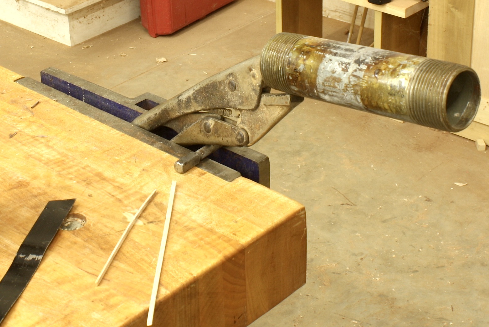 In woodworking, one of the most satisfying things is that you never know it all. Everyday there is something knew to learn. That’s one of the things that keeps me looking and listening and trying new ideas. In the left-hand photo, you see how I’ve set up to bend stringing since I first began working with the material. I grabbed a length of pipe in Vise-grips, clamped it into my bench vise, heated the pipe and bent the stringing over the pipe using a metal-strap backer. If you look close, you see a nail set slipped between the grips and vise. I sometimes found that downward pressure as the bend was taking place could cause the setup to move in the vise, and that’s not a good thing to have happen. The nail set stopped that.
 There’s always something new to learn in woodworking.