Category Archives: Power Tools

LVL Desk in a Weekend

Steve's deskIt’s a holiday weekend. Yeah. I have an extra day in the shop on Monday that I intend to fill building a quick desk with my younger brother. He’s looking for something a bit toward contemporary and I’ve sold him on using LVL (Laminated Veneer Lumber) for the top with legs that are simple to make; he wants inexpensive and quick. The most time spent – at least I hope it takes longer than other parts – is time building a pencil drawer.

I took two hours to rip, square and assemble the pieces of LVL for the top one night after work. That includes time spent watching glue dry. The process is easy. Here are the steps in case you want to play along (or build something similar down the road).

2M4A2152I began with two LVL beams that were 1-3/4″ x 11-7/8″ x 10′-0″. After chopping the beams in half lengthwise, I set up at the table saw to rip each piece to 2-1/8″. Of course, one edge was ran over the jointer to give me a square edge to start. Using a 50-tooth combination blade, LVL cuts easy. The beams I purchased had a bluish painted surface, as you can see in the photo. That worried me little after making the jointer pass. Then after ripping the pieces and turning them on edge, you begin to see the final surface. To make up the 30″ in width needed to the desk, I ripped all four half beams, which produced 20 strips that were 1-3/4″ x 2-1/8″ x 60″+.

2M4A2153
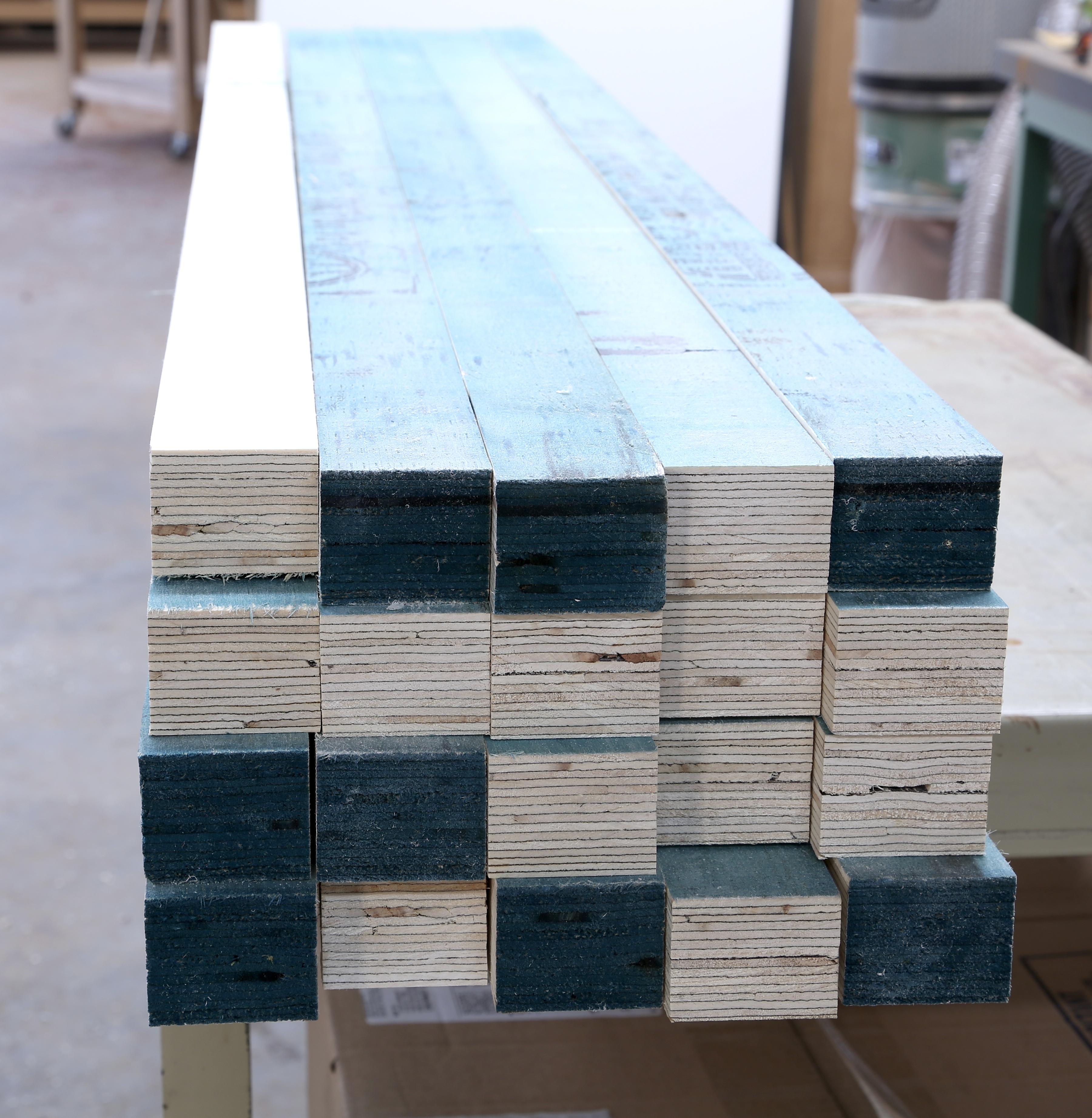
From the table saw, I returned to the jointer to true one of the two yet-painted edges to provide a solid glue surface. A single pass flattened all but two of the pieces. Those two pieces were areas where the lamination overlapped causing a bump in the face. I ran them a second time in order to achieve a flat face. You still see bluish paint in the left-hand photo because only one face has been flattened (all faces run over the jointer knives are downward facing, waiting for the planer.

2M4A2156A ride through the planer was so easy. All I needed was to flatten the second face for glue. The planer I used is setup with a spiral cutterhead. Even though there were no problems with the three-knife arrangement at the jointer, the planer surface was smoother. (This is why, when asked, I suggest that the planer have the spiral cutter, but it’s not that important on your jointer – the jointer is seldom the last surface of your work.) The first pass was great except for, you guessed it, the two pieces that needed the extra pass at the jointer. When those two were feed through the planer, the final surface was untouched in a couple places. A send pass through the planer was required, but only for those two pieces.

To my surprise, the most difficult process in assembling the two planks for the top was the glue-up stage. Spreading glue on the 19 pieces (yep, I had one strip left over after attaining the 30″ width) was a pain. 2M4A2159I decided to lay the strips out as if I were gluing panels for a case side. With the finished face up, I then rotated each piece to a glue face. With the pack tight together, I squeezed glue up and down the face leaving small lines covering the surface. I spread the glue using a thin scrap of wood. Scraping along the length was no good, but across the pieces worked like a charm. With one side gooey, I flipped the strips abd slathered up the second side. I was amazed at how sticky the pieces were as I tried to align the ends – I needed a mallet to move the individual pieces. Than goodness I assembled the 19 pieces in two separate groups. When finished, I added clamps and let the half-tops set. All in all, I used almost 3/4 of a quart of glue.

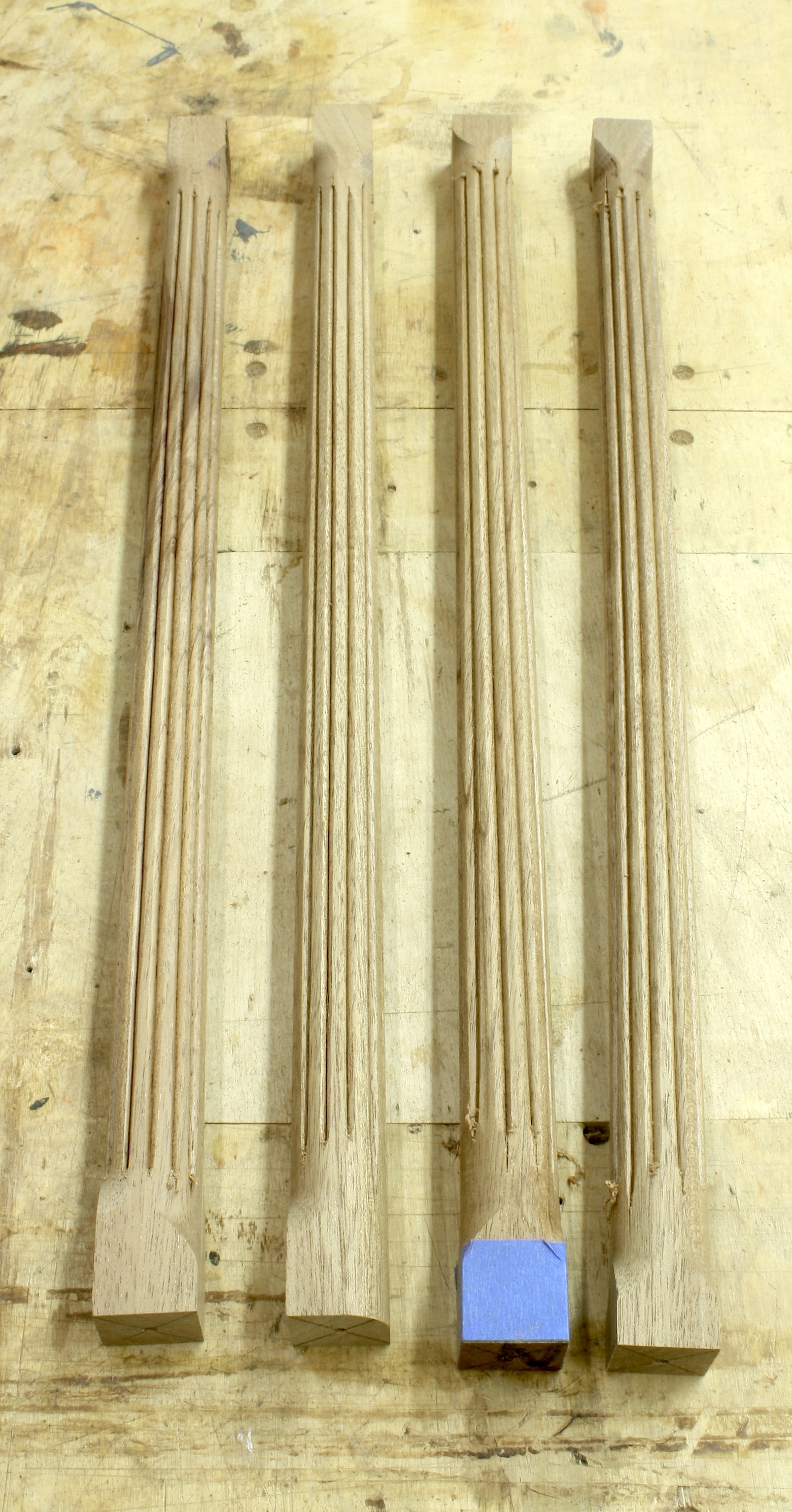
Out of the clamps in 45 minutes and all that was left was to clean the squeeze-out off and make a pass through the planer to level the two surfaces. When slid together – I still need to assemble the two halves – you get a good idea of how the top looks. My guess is it’s even better when a bit of finish is applied. Next week I’ll walk through the legs. Get it?

Build Something Great!

Glen

2M4A2161(1)

2 Comments

Filed under Desk Build, Methods of Work, Power Tools, Shop Tips

Karen’s Inlaid Box (PartIII)

IMG_1694Yesterday was family day, so if I was going to get anything done this weekend, it would have to be in the shop today. I had a few things to catch up on, and I planned to inlay the box I’m working on. After I fixed a drop finial that was broken off my highboy and reshaped a few brass mallet inserts, I installed hinges on the clock waist doors then got to the box.

IMG_1682The first order of business was to make the fans. I decided to make and use fans with three sections instead of the four sections in my original drawings – four sections were too wide for the box front. I sand shaded the fans a little just to provide a hint of visual depth. I then laid the fans onto the box front to arrange a pleasing layout.

IMG_1683Once I had the layout set, I traced around the outside of the fans. One thing to remember is to flip the fans as you transfer the layout. Otherwise you could find yourself positioning a fan with its less-desirable face up because sometimes (most times) the fans are not perfectly symmetrical as to allow it.

IMG_1685The next step was to waste out the area where the fans fit. I worked the first fan recess by routing out the waste then setting the lines using my chisels and a #3 carving gouge. On the second recess, I struck the lines then routed away the waste. (I did the third fan recess this way as well, but as far as I can tell, there is little difference. Both methods work equally good. Cut as close to the line as you can without nicking it, then clean away the balance using the chisel.

IMG_1689The fans were glued in place using regular yellow glue just before I left for lunch. When I returned about an hour later, I first sanded the top, ends and back of the box to #180 grit. I then peeled the blue tape from each fan. As I looked at the box, I thought it looked a bit plain. Because I have no set box to create (I’m free-wheeling it), I decided to add another spot of inlay.

IMG_1691I settled on a small blackwood dot above each fan. To make the dots, I used a 3/8″ plug cutter then sliced the discs off using a handsaw – that way I could control the thickness of each disc. The recesses for the dots was nothing more than a shallow hole from a Forstner drill bit. Once the holes was cut, I dropped a bit of glue into the hole and set the disc in place. After the glue had enough time to dry and after I had cut, shaped and installed a simple handle in the lid portion of the box, I leveled the front of the box as shown in the opening photo.

I add a couple hinges during the week, and I hope to use rare-earth magnets to keep the box closed. After that, I’ll apply a few coats of my oil/varnish mixture and that should do it. If I missed anything that you’d like to know, please drop your question in the comment section below. I’ll get you a reply in short order.

Build Something Great!
Glen

2 Comments

Filed under Hand Tools, Inlay, Power Tools, Routers

Karen’s Inlaid Box

Karen_DogsWatching shellac dry is not much fun, so as things progress on the tall clocks I decided to knock out a promised-to-build, small box. It is close in design to the tea caddy I built for a magazine article a couple of years back. This box doesn’t use edge banding, so the work is a bit easier. The artist rendition (actually my drawing from SketchUp) looks too red; I’m building the box out of mahogany and using tiger maple for the trim pieces. I’m writing about this not so much for the value of the project, but more for the techniques I use as I build – there are methods used that can be employed on other projects.

The four horizontal parts of the box were milled to size and thickness. I made the pieces 1/2″ thick; width and length are your call if you’re building along. The first big step is to bevel the ends of each piece, and you know there are many different methods you can use. I choose the table saw for a couple of reasons: IMG_1656It’s easy to use, I can set up the miter gauge to be square and once the blade is set to 45°, I can use the same setup for two operations. The photo (at right) shows the setup used to bevel the ends. A sacrificial fence with a cut ran through it after the blade was beveled, makes it easy to locate the box parts to trim. I also added a stop-block to keep the parts from creeping away from the blade as the cut is made. One additional point you should glean from this image is my hand placement. My first inclination was to grab the gauge with my right hand and hold the part with my left. If that happened, my left arm would – at some point in the cut – completely block the blade from my view. That’s not good.

The next cut to make is for a spline to run up the corners. I learned a long time ago that making a 45° cut into a previously cut 45° bevel results in a cut that’s 90° to the bevel cut. (What did he say?) IMG_1657Using the same table-saw setup but placing the gauge on the opposite side of the saw blade, makes the next step cake. Once again, make a pass over the blade to establish where the cut hits the sacrificial fence to use to align the parts, then position one piece to that kerf. Make sure to dial back the blade height, then clamp a stop-block in position to use as a guide for each cut. Notice how I switched my hand placement for this round of cuts.

IMG_1658I’m going to set the box bottom inside the four horizontal parts, so I need a groove cut along the bottom edge. Many woodworkers would gravitate to a dado stack for this step, but to me, this is a waste of time. A couple of passes with the blade set to the correct height and the fence properly positioned and you’re done with the groove. Easy, peasy. And there’s no need to swap blades.

The action is picking up. Next step is the bottom. This I made from tiger maple. (Yes, I know you’re not going to see the bottom most of the time, but I have so much scrap tiger maple around my shop it’s a crime not to use the smaller cutoffs for something.) IMG_1661To rabbet the edges to fit into the roughly 1/4″-wide grooves, I use a two-step method at my table saw – what can’t you do with this machine? The process is straightforward. After you get the necessary measurements from the box parts – you can measure the width and length right in the grooves of the front and end – cut the bottom to size (you may want to go a bit less in width to accommodate for any seasonal movement if your box is on the wide side. The first pass is with the bottom face down against the table top – set the blade height to leave a 1/4″ of material after the cut. I make a 3/8″-wide rabbet to make sure the edge doesn’t interfere with the box as it goes together. The next step is to readjust the blade height to just tick the top edge of the previous cut (with the part standing on edge at the fence), and to set the fence to leave the tongue thick enough to slide into the groove. While it doesn’t make much of a difference here, it’s good practice to run the end-grain cuts first.

IMG_1662After you cut pieces to fit into the spline cuts, it’s time to assemble the box. Two points to make here: Your splines cannot run from top to bottom – you need to stop them at the groove or your bottom will not fit, and only assemble the box at two of the four corners at the beginning. If you do glue all four corners, make sure you install the bottom as you assemble the parts. I like to glue half the box, then slip in the bottom and finish the assembly later. Working all four corners and the bottom at the same time can get busy. Add a few clamps and set things aside.

After the glue dries, slip in the bottom, add glue to the remaining splines and corners, then put the clamps back in position and let it set.

IMG_1664

In a later-to-come post, I’ll add a top to the assembled box, split the lid off the base then add some trim pieces. After that, I’ll make the fan inlays to complete the box.

Build Something Great!

Glen

2 Comments

Filed under Joinery, Methods of Work, Power Tools

Different Blade Connection

6-Dr_Chest_Complete-1Wonder what blades are? It’s simple. In furniture speak, blades are another name for drawer dividers. As you probably know, there are many techniques and joinery methods to attach drawer blades to the case. The technique shown here is one that is not all that common, but it is found in antique furniture, namely the Moses Bayley high chest of drawers from Newberryport, Mass. (There is a fascinating bit of history surrounding the highboy; read more about it here.)

In the first issue of American Woodworker magazine under the complete guidance of F+W with me as the content director, I built a chest of drawers (shown above) using this blade connection technique – the issue should be available sometime in early June. (You and 100,000 of your closet friends should pick up a copy!)

B_SlotThe process is easy. While the connection could be done without plowing an 1/8″-deep groove, it’s easier to do so and the groove adds another detail to your work. Step #1 is to rout the groove – align a straightedge to your project, then run a router and 3/4″ top-mount bearing router bit along its length as the bearing rides your straightedge. The width of the groove has to match the thickness of your drawer blades.

Step #2 is to form the dovetail on the ends of your blades. The length of the dovetail – how high you need to raise your router bit – is equal to the thickness of the material remaining after the groove is cut. A_DovetailIf you’re using 3/4″-thick material, after the 1/8″ groove you have 5/8″ of thickness remaining. For me this is a bit of work completed at the router table. Set the height of the bit then adjust the fence so its aligned with the router bit exactly at the table’s top edge. This takes advantage of the entire thickness of your blade – if you’re slightly thinner after your cut, that’s OK, but do not leave a flat on the edge of the dovetail. (Notice the solid push block used to guide the tall drawer divider through the cut.) After you have the dovetail ends created, cut away the back edge leaving a 1″-wide dovetail – trim the dovetail away flush with the square shoulder on your blade.

C_LayoutStep#3 is to transfer the dovetail profile onto your case side. As you can see in the photo, the blade slips into the groove and the trimmed dovetail sits tight to the case side. Using a sharp pencil, transfer the profile. Nothing fancy here. No special details to share. Simply install the blades into position then draw the lines. Bingo.

Step #4 is to square the layout lines down the case side 1″ (matching the dovetail width), then draw a straight line setting the bottom of the socket. D_SawIt’s time to define the socket. This is where your ability to saw comes into play. Cut the two sides of your layout down to the inch mark. Follow both lines as you saw. After you’ve established the socket’s outer edges, make a few additional saw cuts between the lines – the more kerfs you have, the easier the next couple steps become and the cleaner your socket will be to work.

Step#5 is to break out the thin pieces of wood that fill your socket. E_PareYou can jam a chisel into the slots, or if they’re thin enough, you can break the pieces out with your fingers. The neat things is that when they break – due to the grain orientation – the slivers break flush with the bottom edge of the socket. (Sometimes they do break slightly above the line.) With the pieces out of the way, pare the socket bottom so it’s smooth and level. Make sure the socket is level from outside to inside. And it wouldn’t hurt to slope a bit toward the inside – that guarantees you’ll have a tight fit on the exterior of your case.

The last step is to fit the blade’s dovetail into the socket. F_FitIf you’ve sawn to the layout lines and trimmed the socket even at the bottom, your blades should fit easily. Brush glue onto the dovetail and into the socket (the best glue surface is the flat-grain to flat-grain connection at the bottom of the socket), then drive the workpiece home. By the way, don’t forget to repeat these steps twice for each drawer blade or divider. Test-fits are terrible with only one socket cut.

I’m not going to show you a finished shot of the chest of drawers – for that you’re going to have to wait until the issue is sent – but I will show you a photo of the highboy mentioned above. In fact, if you’re so inclined to want to see this process in action, I have a full-length DVD on building the Moses Bayley chest. You can purchase a copy here.

Build Something Great!

Glen

G_MA High Chest

2 Comments

Filed under Antique Pieces, Hand Tools, Joinery, Methods of Work, Power Tools, Routers

One Becomes Three

Photo courtesy of H. L. Chalfant Antiques in Wets Chester, PA

Photo courtesy of H. L. Chalfant Antiques in Wets Chester, PA

When talking about antique chest of drawers, “chest speak” often mentions drawer layout to describe a piece. You’ll read in a magazine advertisement, in an auction catalog or on a web site that it’s a three-over-five design, or a two-over-three-over four design. What is being described is the number of drawers stacked over the next bank of drawers. The first example would be three drawers set in the top row with five full-width drawers set below. The second example would have two drawer in the top row, and three drawers that make up the second row, with four full-width drawers stacked below. (The top rows are often reversed as shown in the opening photo.) Combinations are endless, but you don’t often see numbers get out of hand.

There is something to keep in mind as you look at drawer layout. Is the bank of drawers actually divided into two or three drawers, or is that a single-width drawer made to look like it’s divided? If it’s a single drawer made to look like three, what’s an easy way to duplicate that if you were building the chest? One way is to use an ovolo router bit.

An ovolo bit is similar to a roundover router bit, but there is nothing attached IMG_1599to the bit to guide it path – no pilot (that’s a throw-back design) or bearing such as what we have on most roundover bits. In the right-hand photo you can see the difference between the two different bits that basically cut the same profiles. Both router bits shown have a 1/4″ roundover profile. (Click the photo to enlarge the image.)

The way to use an ovolo bit is to first profile the edge of your drawer front using a roundover bit. Next, chuck the ovolo bit into your router, set the depth of cut to match the roundover profile, clamp a straightedge to the workpiece and run test cut. Measure the distance from your straightedge to the exact center of your ovolo profile. You’ll need that as you layout for the cut in your drawer front. (With my ovolo bit the width of the completed profile is 1″.) Layout work can be tricky. If you don’t pay attention, it’s easy to get the faux fronts a bit off in width.

IMG_1602

Once the layout work is done, measure from the layout line to where you need to set your straightedge, clamp it in position and you’re ready to divide your drawer front. Work slow as you rout, it’s easy to flip out the profile as the router bit enters the cut.

How can you tell the drawer front is not really three individual drawers? Look closely at the vertical divider areas. You’ll see a small gap at the top of each divider if the drawer front is a single-width front and the furnituremaker was attempting to fool your eye.

Build Something Great!

Glen


Leave a comment

Filed under Antique Pieces, Design, Power Tools, Routers

The Best Dovetails

If you came here looking for the perfect set of dovetails – the best layout, the best ratio of tail width and pin width or the thinnest pins ever cut – you’re going to be disappointed. This post is not about that. It’s about dovetails that are never to be seen. It’s about what I call structural dovetails.

IMG_0084Structural dovetails are the best dovetails because these joints can have over-sized tails and pins, and this is where you get the opportunity to either bang out a set without regard to the above mentioned conditions, use alternative methods to cut and fit your joints or practice in an area that will not see the light of day – why practice on a scrap when you can contribute to your project while building your skills. For me, alternative methods of work is my focus.

This is a point where I can pull out tools that are seldom considered when cutting dovetails. Tools such as my jigsaw and router. This is where I experiment to determine if there are better ways to work – and I still move ahead on my project.

49If  you’re scratching your head at the mention of my jigsaw, or if you’ve never considered using your jigsaw to cut intricate joinery, you’re in for a treat. I often use my jigsaw to cut dovetail pins and tails. (It’s best if you turn down the variable speed setting to gain additional control of the cut.) And I’ll bet you a dollar to a doughnut that you couldn’t tell which joints were cut using the jigsaw and which joints were sawn by hand.

Let’s being with pins, or wasting away the tail waste. Jigsaw blades can be angled in either direction, and set to most any degree of angle; I use 12° for my dovetails. The photo above shows how you can make the cuts to define the pins. Set the angle to the right or left, then cut all the pins on that particular side. Switch the angle to cut the pin sides in the opposite direction. Done.

51To pull the remaining waste from the socket, it’s the jigsaw again. Set the blade back to 90°. With the show face down, swoop in from one side of the waste as you cut toward the baseline. As you reach the baseline, swing the jigsaw to cut parallel to the line but about an 1/8″ away. As you reach the end of the waste, slowly kick your saw back on its heal to increase the angle of cut until the portion of waste falls away. It takes getting used to, but you’ll pick it up in a hurry. Besides, if you nick the pin, who cares because it will never be seen. After you finish working in one direction, turn around and use the same technique to trim away the remaining waste. That 1/8″ that’s left is easily peeled away using a sharp chisel. You also can cut the pin waste using you jigsaw; I sometimes do that when the panel I’m dovetailing is too large to hoist up to my band saw.

IMG_1519

Fooling around with structural dovetails is also when I began using my router to waste away tail socket waste. If you haven’t s seen this technique as of yet, you owe to yourself to take a look. The results are dead-flat bottoms that dam near guarantee square boxes when you’re done with assembly. (Watch a short video here.)

Next time you’re working on structural dovetails – the best dovetails – try your hand at a few unconventional woodworking ideas. You may find something that works beyond your wildest expectations.

Build Something Great!

Glen


2 Comments

Filed under Joinery, Methods of Work, Power Tools

Door Frame Fix

When I began building the Egerton tall clock, I built one base, waist and door before deciding to build a second clock. As I completed the door on the second clock, I moved to the hoods without fitting the door to its opening. Mistake. Big mistake.

Nearing completion of the two clocks, the time arrived to fit the door. No worries. I setup my router with a rabbeting bit, IMG_1501ran the bottom, left side and top, leaving the right side for the hinges – that side has only an 1/8″ rabbet. I carried the door to the case, but it didn’t fit. The arch at the door’s top wouldn’t fit into the opening when the balance of the door was in place. I remembered that the arch pattern I used was off center – a design feature specifically chosen to keep the arch centered in the waist when rabbeted to fit. If I would have made the rabbet cuts so the door hinged on the left side instead of the right, my work would have been done. Crap.

After thinking about possible fixes for the week, yesterday I headed to the shop with a plan: Cut away the current piece from the door frame, then install a new section that was cut to fit and laid out using the door itself. To attach the new piece, I had a long-grain connection at the top edge. The ends, however, needed something for hold. I decided a half-lap at each end would be perfect.

To make this happen, I setup my router and grabbed a piece of plywood scrap that IMG_1502had a perfect 90° corner intact. The distance from the edge of the router’s base and the far edge of the straight bit I loaded was found. I then added another 1/2″ to allow for the half-lapped ledge. I positioned the makeshift, plywood fence that distance from where the rail and stile met on the door frame and was ready to cut.

I set the depth of cut to just remove the entire thickness of the rail, and made the cut. IMG_1505The fence was then reversed to work on the other side where I followed the same process. With those two cuts made, I adjusted the depth of cut so half the total thickness of the rail was removed, positioned the fence so the router bit cut exactly at the rail/stile intersection and trimmed away the material as shown in the left-hand photo. The center section was simply free-hand cut once the fence was removed. All that was left to waste away was the top edge.

I set the fence in place to work the same magic along the top edge, then made a shallow test cut so I could dial-in the exact setting. IMG_1506It took a couple of tweaks because I wanted to remove the rail without cutting away any of the tri-colored stringing just above. Once I had the fence just where I wanted it, I adjusted the bit depth and made the last pass. As I reached the end of the cut, the old rail fell away. Perfect. I grabbed a chisel to clean up the corners and square any rounded portions left from the router bit. Time to fit a replacement.

I spent a little time getting the new rail sized and tightly fit to the existing framework. The ends of the new rail were easily rabbeted using my table saw. IMG_1509With the replacement in position, I put the door in place then drew a pencil line around the rabbeted arch of the door. The rail was pulled from the clock waist, a cut at the pencil line was made using my band saw, the raw edge was sanded at my spindle sander and the replacement was then glued into position. The long-grain edges mated up and the half-laps worked great. When the glue was dry, I sanded the surfaces flush and called it done. Everything went according to plan and much quicker than expected. I call that a great day in the shop.

Build Something Great!

Glen

3 Comments

Filed under Jigs, Power Tools, Routers, Tall Clock

Bump-cut Band Saw Tenons

IMG_1439Because I had to make the columns on my tall clocks longer than needed so I could form the reeds with my scratch stock, each column needed to be cut to length. (The blue tape held together a fracture at the end of the column – I use this same technique when turning, if need be.) Once at length, each end of the columns needed to be reduced in diameter to fit into the brass capitals. Then ends of the individual reeds are then shaped further.

My first thought was to load a column at my lathe and turn the tenon before I cut the pieces to length. I want a snug fit through the capital, and there would be no way to check the fit while on the lathe – there was about 2″ to remove off each end of the columns, so I couldn’t simply slide on the capital. IMG_1440If I cut the lengths first, I lost the center markings and, for me, that makes loading the piece on the lathe too much of a hassle (I’ve not had success remarking the center whether using a center-marking gauge or not).

What I decided to do was to cut the columns to length, then use my band saw to form the tenons – it’s a similar operation as making a bump-cut tenon using a table saw. (You can see a short video of this technique here.) In the photo above right, you see the end of the columns after its been cut to length. (You can also see that there is more work to do on the reeds.) And below you can see my setup at the band saw.

IMG_1443

I used a bench hook to guide the stock, and used a spacer (set between the hook and band saw table) to locate the hook fence just beyond the blade. This setup is somewhat critical. If you’re too far beyond the blade, you will remove too much material. (If you’re in front of the blade, your tenon would be too fat.) I say that setup is somewhat critical because you do have a little adjustment. IMG_1445That comes from moving the band saw blade forward or back using the guide bearings on the saw. A simple tweak can push the blade forward to allow you to dial in the best cut. I went for a tenon that was just too snug to fit my capital so I could lightly sand the tenon to fit. The photo shows a closer view of the setup. (Click on the photo to see it even larger.)

I positioned the column tight to the second block – that piece has a 1/2″ notch which is the tenon length, and I’ve clamped it tight against the bench hook to make sure the two are aligned. With the column set against the second block, I spun the stock to cut the tenon shoulder. I then nibbled away the waste in one area of the tenon – it takes a bit of wiggle and movement. Once that area is flat and clean, I began the bump-cut technique. IMG_1446Back and forth into the second block while rotating the column; it’s like rubbing your head as  you pat your stomach.

When a full rotation is finished the tenon is formed. Two clocks, four columns per clock and two ends per column left me with 16 tenons to form. Taking the time to set up this method saved me time in the long run. And I didn’t waste a column that needed to be replaced with another – that would have burnt at least an hour of shop time.

Build Something Great,

Glen

Leave a comment

Filed under Jigs, Power Tools, Shop Tips, Tall Clock

Router-made Columns

IMG_1410Last week I finished the work on the goose-neck mouldings and the carved rosettes. At the left, you can see the mouldings and rosettes in place (click the photo to make it larger). This week I turned my attention to the columns that flank each side of the hood at the front and back.

These columns are reeded and need to fit a 3/4″ opening in the brass capitals. To make things work, I need to make the columns a larger diameter, then create the reeds, which extend beyond the 3/4″ diameter. I decided to make the columns 1″ round and to scratch in the reeds. The extra diameter allows for the reeds and provides a bit more material if needed.

My first thought was to turn the columns at my lathe. Even with a copy lathe, the process is slow and laborious – I need eight columns, four for each clock (I’m building two). IMG_1411There is no shape to these columns. No undulating whatsoever. They are straight from top to bottom.

After the first column, I remembered a technique to produce round dowels using a router table setup. It’s way faster. All you need is the correct router bit and material that is about 4″ (2″ extra at each end of the column) longer than the final length of the dowels. The router bit is a round-over bit that is half the total diameter of your dowel. IMG_1414In this case I am making 1″-diameter dowels, so I need a 1/2″ round-over bit. (If your dowels were 3/4″, you would need a 3/8″ round-over bit.)

I needed 16″-long columns. To work this technique with the added 4″ of material, I needed a minimum table length of 34″ (twice the column plus 2″). My router table top is nowhere near that length, so I whipped up an auxiliary top made from a piece of 1/2″ Baltic birch plywood. I positioned the router bit so the bearing was flush with my fence, and set the height just even with the top edge of the plywood.

You need to pivot the material into the cut so you leave a short section of square material at the leading end. As the material contacts the fence, cut the profile just as you would normally do, but do not run through the entire length. IMG_1416At the trailing end, stop short, leaving 2″ or less of square material. It’s those square sections that keep the dowel from turning as you make the last pass.

After you complete one pass, rotate the material 90° and make another pass. Four passes later you have a rounded dowel that rolls across your bench.

I completed all eight dowels (plus an extra just in case) in about 15 minutes after I had the setup ready to go. Wham. Bam. Thank you, ma’am.

IMG_1417

Now to come up with a way to hold the dowels as I scratch the small reeds. I remember seeing a setup that Jeff Headley concocted for a similar purpose. Think I’ll dig that up.

Build Something Great!

Glen

Leave a comment

Filed under Methods of Work, Power Tools, Routers, Shop Tips, Tall Clock

Goose-neck Mouldings

Kasper Bonnet TopGoose-neck mouldings are, in my opinion, the great equalizer in any discussion of moulding planes or power tools for curved designs. Sure straight runs of moulding can be made using hollows and rounds, but the curved mouldings are a completely different animal. With goose-necks, you better be thinking kindly about a router, router table or shaper. And, you probably should have a selection of carving tools if your design has a rosette and doesn’t return on itself (as shown in the above photo).

#5024-01Of course, the Egerton clock has rosettes. This translates into more hand work using carving chisel. But the bulk of the waste is removed with power tools. You just need to find the correct profile, and that can be tricky as you flip and turn the profile looking for a match, especially if you’re using bearing mounted router bits. (I’m tossing out shaper work, because most woodworkers are not working with a shaper – router tables have all but replaced the shaper in home shops.)

The best way to run these profiles using a router is with the face of the goose-neck moulding facing up. To do that you need an over-arm pin router setup, or you need to create a method to hold your router above the workpiece as you guide the cut, as shown to the left. Router_JigThis setup uses the guide-fence holes and scrap pieces to raise the router cut abilities. The setup is easy to duplicate, but using the arrangement is not that simple. You need to accurately guide the router along the curved lines of the goose-neck while holding things at 90° to the workpiece. Slow and steady wins the race, but even then you have clean-up work to do. It is much better if you can use bearing-mounted router bits. To do that in this scenario, I had to run at my router table, keeping the face of the mouldings against the table.

The problem with bearing-mounted router bits is reach. On wide goose-neck mouldings, you often cannot reach back into the profile enough to make things work. IMG_1399On the Egerton moulding, though, that’s not a problem because it’s only 7/8″ wide. I was able to use the bearings on my router bits of choice to get the job done, so the first bit used was a cove design for raised panels. That router bit allowed me to reach back 3/4″ of the 7/8″ needed – that left an 1/8″ of flat at the top edge of my profile. On the straight runs, cut from end to end. On the curved work, you need to stop just short of the rosette area.

The second profile I used was a simple 1/4″ round-over bit, but I switched out the normal bearing to use one that was a 1/8″ smaller in diameter. IMG_1401That change moved the round-over profile in slightly on the workpiece. Height adjustments need to be accurate. Because I was looking to flow the second profile into the larger cove cut, I found it best to sneak up on the final setting. I could have stopped at this point, but the square edge left after the second router cut was smaller than what I saw on the original clock profile. I wanted more.

Deciding to make the last router-bit cut added the needed square-edge to my profile, but it also caused more work after routing work was complete. IMG_1403To achieve an additional 1/16″ of square edge for an 1/8″ total, I used a rabbet bit to push the design up into the moulding. That cut removed a lot of the round-over profile, but that would be easy to replace with carving tools, and the extra square edge made the design of my goose-neck more in line with the original.

To complete the mouldings, both the curved and straight pieces, I use a couple carving gouges to re-round the profile. Work on the straight pieces was easy. I found and carved with the grain direction. On the curved pieces, carving required that I move in different directions due to the grain changing as the curves undulated. Even with that need, the work was not difficult.

Next week I’ll show the completed and installed goose-neck moulding with the carved rosettes in place. I’m getting close to finished.

Build Something Great!
Glen


1 Comment

Filed under Hand Tools, Jigs, Methods of Work, Power Tools, Routers, Tall Clock