Goose-neck mouldings are, in my opinion, the great equalizer in any discussion of moulding planes or power tools for curved designs. Sure straight runs of moulding can be made using hollows and rounds, but the curved mouldings are a completely different animal. With goose-necks, you better be thinking kindly about a router, router table or shaper. And, you probably should have a selection of carving tools if your design has a rosette and doesn’t return on itself (as shown in the above photo).
 Of course, the Egerton clock has rosettes. This translates into more hand work using carving chisel. But the bulk of the waste is removed with power tools. You just need to find the correct profile, and that can be tricky as you flip and turn the profile looking for a match, especially if you’re using bearing mounted router bits. (I’m tossing out shaper work, because most woodworkers are not working with a shaper – router tables have all but replaced the shaper in home shops.)
The best way to run these profiles using a router is with the face of the goose-neck moulding facing up. To do that you need an over-arm pin router setup, or you need to create a method to hold your router above the workpiece as you guide the cut, as shown to the left.  This setup uses the guide-fence holes and scrap pieces to raise the router cut abilities. The setup is easy to duplicate, but using the arrangement is not that simple. You need to accurately guide the router along the curved lines of the goose-neck while holding things at 90° to the workpiece. Slow and steady wins the race, but even then you have clean-up work to do. It is much better if you can use bearing-mounted router bits. To do that in this scenario, I had to run at my router table, keeping the face of the mouldings against the table.
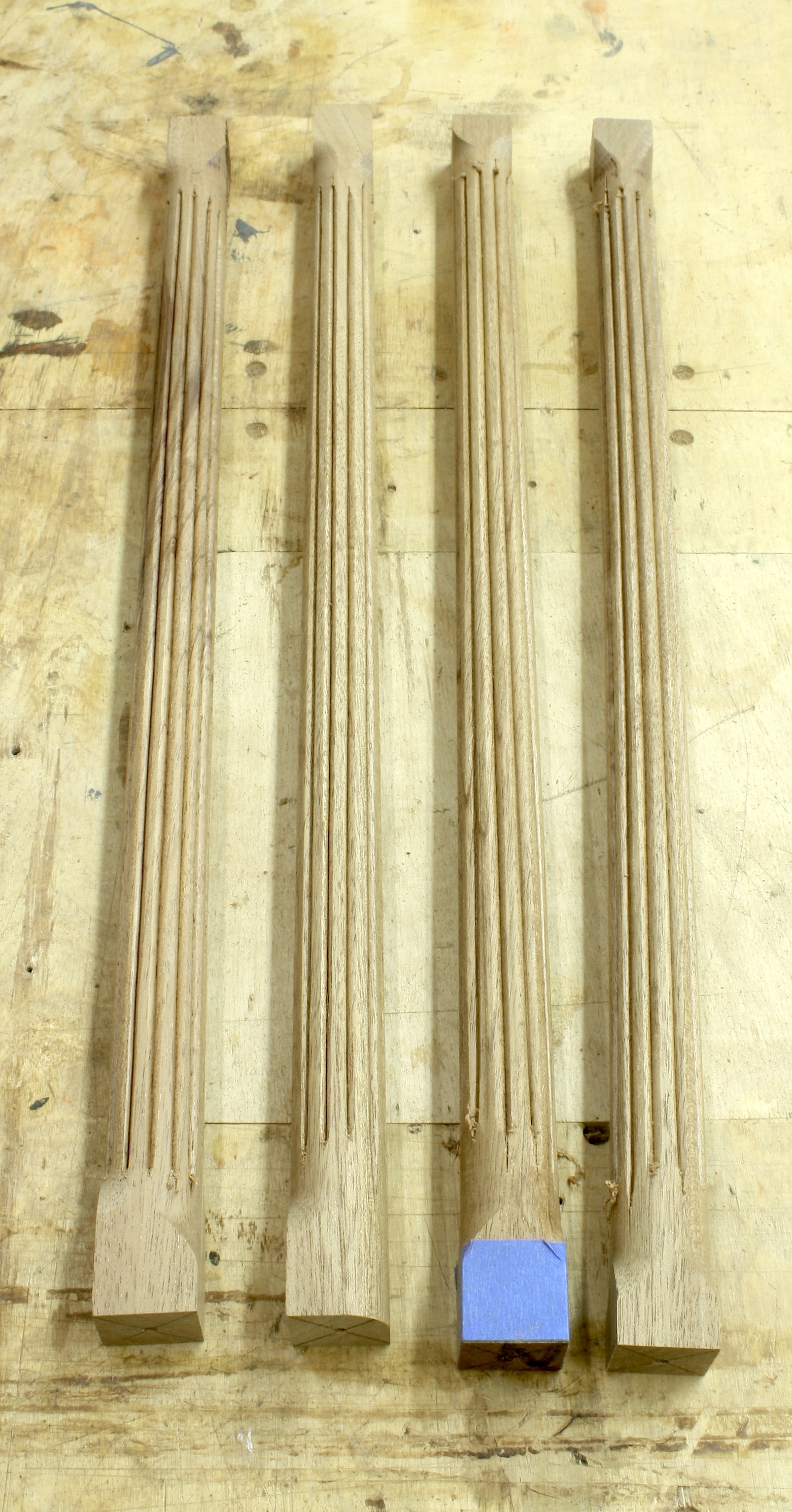
The problem with bearing-mounted router bits is reach. On wide goose-neck mouldings, you often cannot reach back into the profile enough to make things work.  On the Egerton moulding, though, that’s not a problem because it’s only 7/8″ wide. I was able to use the bearings on my router bits of choice to get the job done, so the first bit used was a cove design for raised panels. That router bit allowed me to reach back 3/4″ of the 7/8″ needed – that left an 1/8″ of flat at the top edge of my profile. On the straight runs, cut from end to end. On the curved work, you need to stop just short of the rosette area.
The second profile I used was a simple 1/4″ round-over bit, but I switched out the normal bearing to use one that was a 1/8″ smaller in diameter.  That change moved the round-over profile in slightly on the workpiece. Height adjustments need to be accurate. Because I was looking to flow the second profile into the larger cove cut, I found it best to sneak up on the final setting. I could have stopped at this point, but the square edge left after the second router cut was smaller than what I saw on the original clock profile. I wanted more.
Deciding to make the last router-bit cut added the needed square-edge to my profile, but it also caused more work after routing work was complete.  To achieve an additional 1/16″ of square edge for an 1/8″ total, I used a rabbet bit to push the design up into the moulding. That cut removed a lot of the round-over profile, but that would be easy to replace with carving tools, and the extra square edge made the design of my goose-neck more in line with the original.
To complete the mouldings, both the curved and straight pieces, I use a couple carving gouges to re-round the profile. Work on the straight pieces was easy. I found and carved with the grain direction. On the curved pieces, carving required that I move in different directions due to the grain changing as the curves undulated. Even with that need, the work was not difficult.
Next week I’ll show the completed and installed goose-neck moulding with the carved rosettes in place. I’m getting close to finished.
Build Something Great!
Glen

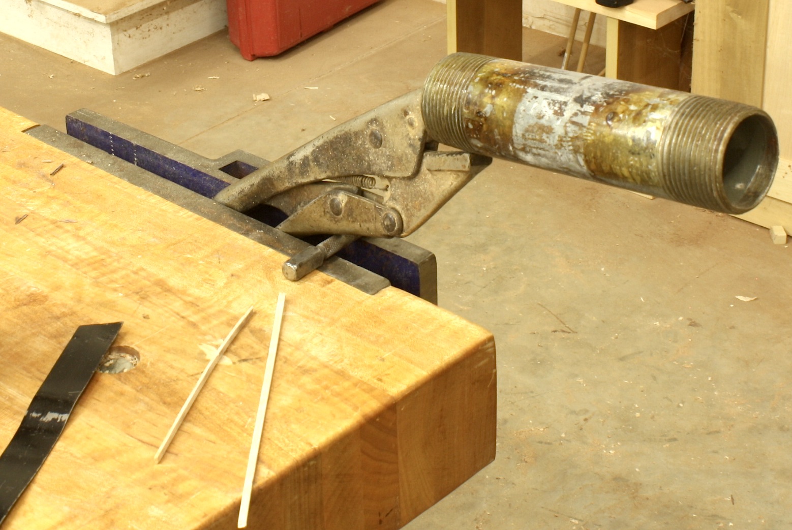 In woodworking, one of the most satisfying things is that you never know it all. Everyday there is something knew to learn. That’s one of the things that keeps me looking and listening and trying new ideas. In the left-hand photo, you see how I’ve set up to bend stringing since I first began working with the material. I grabbed a length of pipe in Vise-grips, clamped it into my bench vise, heated the pipe and bent the stringing over the pipe using a metal-strap backer. If you look close, you see a nail set slipped between the grips and vise. I sometimes found that downward pressure as the bend was taking place could cause the setup to move in the vise, and that’s not a good thing to have happen. The nail set stopped that.
 There’s always something new to learn in woodworking.