Category Archives: Inlay

Always Something to Learn

IMG_1944
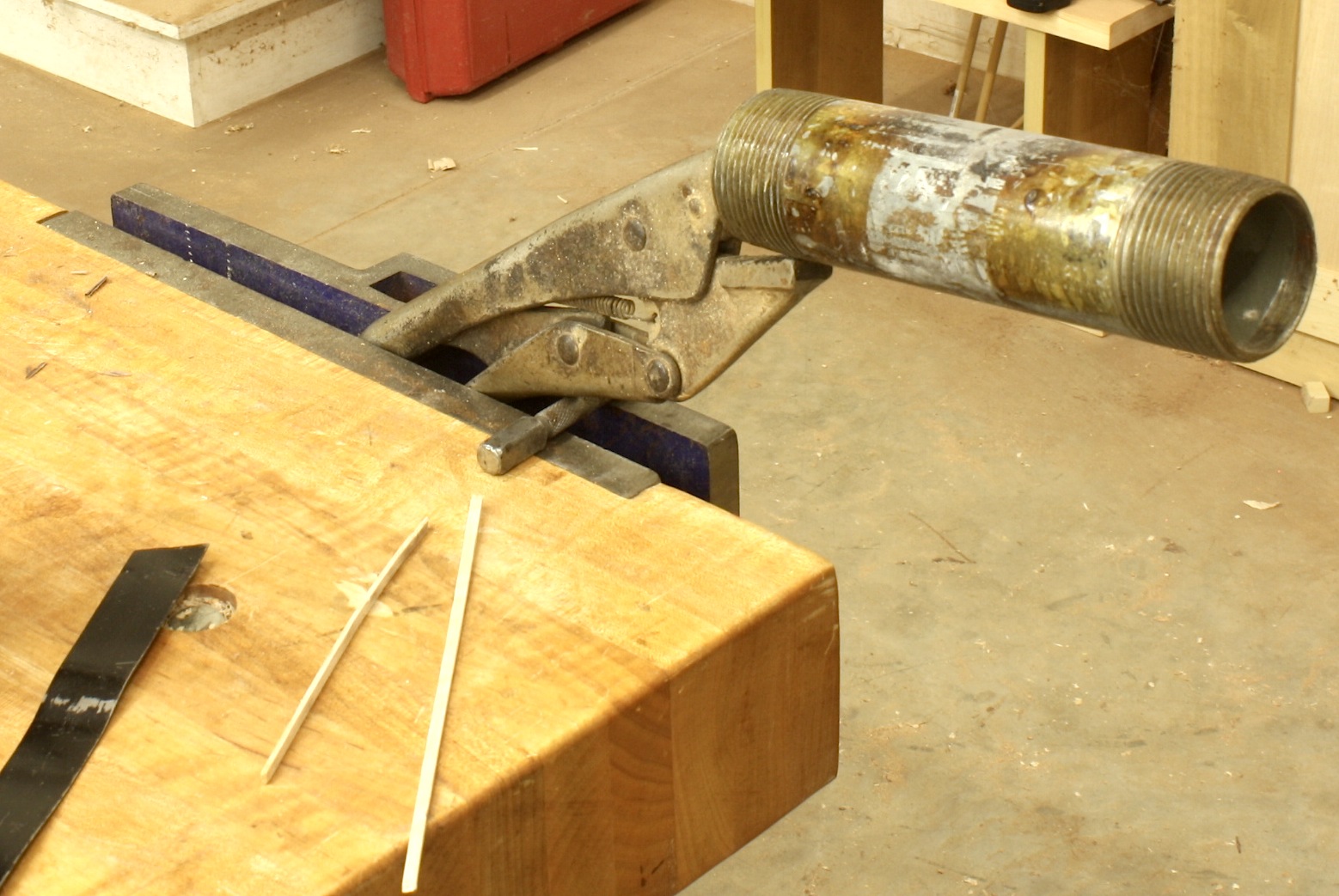
In woodworking, one of the most satisfying things is that you never know it all. Everyday there is something knew to learn. That’s one of the things that keeps me looking and listening and trying new ideas. In the left-hand photo, you see how I’ve set up to bend stringing since I first began working with the material. I grabbed a length of pipe in Vise-grips, clamped it into my bench vise, heated the pipe and bent the stringing over the pipe using a metal-strap backer. If you look close, you see a nail set slipped between the grips and vise. I sometimes found that downward pressure as the bend was taking place could cause the setup to move in the vise, and that’s not a good thing to have happen. The nail set stopped that.

As I’ve demonstrated this technique to different woodworking groups, I’ve had occasion to see a few interesting string-bending setups, including  a massive three-pipe selection that bolted to a workbench and allowed a constant flame to keep the pipe at the correct temperature for bending – whatever that is. I’ve also been asked so many times about using a heating iron as does Steve Latta; sorry Steve, that’s way too slow.

I did, however, learn a new setup while teaching my session at Woodworking in America this past weekend (the reason there was no post on this blog last Sunday). I traveled to Winston-Salem, N.C. without my Vise-grips and nail set. When it came time to demonstrate the technique, I was at a loss. Until, that is, I grabbed the F-style clamp I tossed in the conglomerate of stuff I’d taken along. With the length of pipe secure in the clamp, I set it into the bench vise with the handle resting against the top of the vise. No amount of downward force would cause the setup to move. And as long as you remove any plastic fittings from the clamp, heat from my torch was not a worry. It worked great.

IMG_1943There’s always something new to learn in woodworking.

Build Something Great!

Glen

3 Comments

Filed under Back to Basics, Inlay, Jigs, Methods of Work, Shop Tips

Karen’s Inlaid Box (PartIII)

IMG_1694Yesterday was family day, so if I was going to get anything done this weekend, it would have to be in the shop today. I had a few things to catch up on, and I planned to inlay the box I’m working on. After I fixed a drop finial that was broken off my highboy and reshaped a few brass mallet inserts, I installed hinges on the clock waist doors then got to the box.

IMG_1682The first order of business was to make the fans. I decided to make and use fans with three sections instead of the four sections in my original drawings – four sections were too wide for the box front. I sand shaded the fans a little just to provide a hint of visual depth. I then laid the fans onto the box front to arrange a pleasing layout.

IMG_1683Once I had the layout set, I traced around the outside of the fans. One thing to remember is to flip the fans as you transfer the layout. Otherwise you could find yourself positioning a fan with its less-desirable face up because sometimes (most times) the fans are not perfectly symmetrical as to allow it.

IMG_1685The next step was to waste out the area where the fans fit. I worked the first fan recess by routing out the waste then setting the lines using my chisels and a #3 carving gouge. On the second recess, I struck the lines then routed away the waste. (I did the third fan recess this way as well, but as far as I can tell, there is little difference. Both methods work equally good. Cut as close to the line as you can without nicking it, then clean away the balance using the chisel.

IMG_1689The fans were glued in place using regular yellow glue just before I left for lunch. When I returned about an hour later, I first sanded the top, ends and back of the box to #180 grit. I then peeled the blue tape from each fan. As I looked at the box, I thought it looked a bit plain. Because I have no set box to create (I’m free-wheeling it), I decided to add another spot of inlay.

IMG_1691I settled on a small blackwood dot above each fan. To make the dots, I used a 3/8″ plug cutter then sliced the discs off using a handsaw – that way I could control the thickness of each disc. The recesses for the dots was nothing more than a shallow hole from a Forstner drill bit. Once the holes was cut, I dropped a bit of glue into the hole and set the disc in place. After the glue had enough time to dry and after I had cut, shaped and installed a simple handle in the lid portion of the box, I leveled the front of the box as shown in the opening photo.

I add a couple hinges during the week, and I hope to use rare-earth magnets to keep the box closed. After that, I’ll apply a few coats of my oil/varnish mixture and that should do it. If I missed anything that you’d like to know, please drop your question in the comment section below. I’ll get you a reply in short order.

Build Something Great!
Glen

2 Comments

Filed under Hand Tools, Inlay, Power Tools, Routers

Dressing-up the Keystone

IMG_1394With the moulding installed around the arched opening for the dial, there’s one last detail on the hood before moving on to the goose-neck mouldings of the broken-arch pediment. The Egerton tall clock has a small keystone that separates the two pieces of the arched moulding. The keystone is made from solid mahogany, but the face of the piece is a small assembly of veneer. And by small I mean 5/8″ wide at the bottom, 1-1/4″ wide at the top and about 1-1/4″ from top to bottom. That’s not a lot of inlay, so I can easily get that from scrap pieces already on hand. (Check out the photo. You can see a picture of the original clock between the hoods of the two clocks I’m building.)

To get things started, I thought it best to lay out the design to better get a feel for the pieces and steps. That also made it easy to get the sizes of the maple veneer just right, IMG_1381and that made the work go much quicker. After I had the design, I snapped off pieces of the ebony stringing and cut the small pieces of maple from a leftover sheet of shop-made veneer – I’m tired of sanding through the 1/40″- or 1/64″-thick commercial veneer and vow to never purchase it again. To make sure things went as planned, I stuck the pieces to a piece of tape, then checked the size against the actual keystone.

I was now ready to stick the pieces to the keystone. With a thin layer of glue on the keystone, I positioned the veneer and stringing. IMG_1382(Again, I really like the Titebond No-Run, No-Drip Wood Glue.) A neat technique was to lock one leg of my spring clamp into my bench vise, leaving the other leg operable. This allowed me to easily move or reposition the keystone in any way necessary. At this time, I wasn’t concerned about the length of the pieces applied to the workpiece. I didn’t want them to run past the top and bottom, but I also didn’t need them to be perfectly aligned. After everything was placed and slide to its final position (moving the veneer pieces up or down influenced the overall width of the assembly so I could easily match the keystone face), I set the piece aside to allow the glue to dry.

The next step after the glue dried – about 10 minutes – was to saw the top and bottom edges to add the last pieces of ebony stringing. IMG_1384A marking gauge is perfect to scribe lines to which to saw, and I particularly like a Japanese saw for these types of cuts. With the assembly locked in the spring-clamp vise, I sawed the two lines then peeled the waste parts easily off the keystone. A little more glue was added before I position the two last parts to the face of the workpiece. After the glue dried I used a rasp to level and smooth the inlay, then sanded everything smooth with #180-grit Abranet.

The finished keystone is shown in the opening photo. It’s a small piece that adds significantly to the overall look of the clock. And that’s what inlay does, at least to my eye. Also, if you look at the opening photo you can see the first carved rosette that fits at the end of the goose-neck moulding. I ran through three alliterations before arriving at what I think will work. To get a quick look, I stuck the half-finished rosette in place, then stood back to make a decision. So far, so good. But there is more work to be done.

Build Something Great!

Glen

1 Comment

Filed under Design, Inlay, Tall Clock, Veneer

Egerton Hood

After preparation for Woodworking in America and building a lowboy for the February 2014 issue of the magazine, I finally had the chance to get back to the tall clock. IMG_1363Inlay, both banding and pictorial, were fit to the hood, then I got started on the mouldings. I had a couple of snafus with which to deal, but otherwise things went as planned.

You would think that the bandings – straight pieces of layered ebony and maple – would be the easy work. That, however, is where I had a snafu. One side of the hood went like clockwork. The second edge was laid out just as the first, but somewhere along the line I made the decision to cut away my line instead of leaving it. As a result, I routed a bit wider than necessary. Because the banding is striped, I couldn’t just cut it wider. I had to slice off a couple of the lines then glue back slightly wider lines to make it work. In the end, it was wasted time, but nothing else.

IMG_1360The center inlay was easy. (Read how I made “My Night Cap,” in an earlier post.) Being guided as to position by the design of the hood, I simply clamped the straightedge in place, set the router base tight to that edge and plunged the cut. (No need for a plunge-cut router here; it was easy to tilt the base into the cut to get started.) After establishing one edge, I set the inlay tight to that routed edge and drew the opposite edge onto the hood using a sharp pencil. I then set up the straightedge to just cut inside that second-edge line. I routed the second edge then free-handed the router to waste out all the remaining unwanted material.

IMG_1361With everything ready to go, I added glue to the center inlay recess, and positioned the pictorial piece to the hood, making sure I had a little glue along both edges. A layer of wax paper was slipped over the inlay before I installed two clamps. (After the clamps were in place, I tore off the wax paper to better aid in evaporation to help the glue dry quicker.) The banding at the edges is too easy. And I get to use one of my favorite clamping strategies – blue tape. After spreading glue into the recess – my fingertip sported a heavy layer of glue by the time I was finished  – I slipped the banding into position then added a few pieces of tape to hold everything in place. (Note: I used Titebond No Run, No Drip glue and continue to be impressed with this product.)

Next week I’ll discuss the installation of the bottom-edge mouldings and the center keystone which has to have a small amount of inlay work done before I can stick in place.

Build Something Great!

Glen

Leave a comment

Filed under Inlay, Methods of Work, Power Tools, Routers, Shop Tips, Tall Clock

WIA Class on Inlay

The purpose of my Woodworking in America session on inlay, “Understanding Inlay: A Key Piece in Connoisseurship & Identification” wasn’t to provide rules of thumb to discover the orientation of antique furniture – the idea was to give a few general guidelines that A1_New York Card Tablewould help identify from where a particular antique piece of furniture may have been built. We focused on card tables from the Federal period due to the fact that each major city built card tables from the simplest designs to the most intricate, heavily-inlaid tables. I emphasized throughout the class that the information presented should be grouped with other gathered information so one could draw a conclusion. That stated again, I’ll pass along a few of my comments.

The first and easiest way to identify a card tables point of origin has nothing to do with the inlay, although you could also establish the same origin if you studied the banding and pictorial inlays on the table. Here, however, construction techniques are a dead give-away. The table pictured above is from New York. We know this because of the fifth leg. In almost all cases, if you have a fifth leg, you are looking at a card table built in New York.

ACD_Dunton_NH TableLet’s get back to inlay. The most fascinating of inlay banding, at least to me, is what is known as lunette inlay. There was a time in our furniture study that whenever this inlay was found on a piece of period furniture, that piece was immediately associated with the father and son team of John and Thomas Seymour. Later, a similar inlay was found on other signed furniture not built by the Seymours. That caused dealers and collectors to question the attribution of the Seymour work. The table shown above is a signed piece built in New Hampshire, and not a card table built by a Seymour.

ACC_Bradlys Seymour SimpleAs a woodworker, I wonder how this inlay was made in the period. (The left-hand photo is a close-up look at lunette inlay.) Was it laid up in a pack then sliced as was other inlay? Some woodworker think so. Or was it laid up a stick at a time? There is a camp of today’s woodworkers who think that was how it was done in the late 1700s. Regardless of how you may think it was made, it is a great piece of work and worthy of the amount of study it has received.

DE_Eagle PateraAnother area that I find interesting is to look at the use of eagles in pictorial inlay. The image at the right is a grouping of eagle patera  I pulled together from “American Furniture The Federal Period” by Charles F. Montgomery. (I highly recommend this Winterthur book if you are at all interested in inlay.) If you study the eagles, you’ll notice a few interesting things. First of all, Connecticut inlay – not just the eagles, but most of the inlay work found in this area – is very artistic and quite different from work found elsewhere. Pinpointing period work from the Connecticut River Valley and from Connecticut is rather simple.

Of the remaining eagles, take a close look at the inlay from New York. Notice how lifelike the eagle appears. This eagle looks bold, strong and very patriotic. The Federal period in which we’re looking is right after the Revolutionary war when New York was the nation’s capital, until 1791 when it was moved to Philadelphia before moving to Washington DC. Patriotism had to be extremely strong at the time. Was this strength reflected in the inlay produced at the time?

DEA_Bradlys_Eagle on ClockOne last thought on eagle inlay: If you study the eagles shown in Pennsylvania, Maryland and the South, you’ll see that each of the eagles have something in the mouth, a streaming banner. This could be a telltale of furniture from these areas. Shown at the right is a door from an antique clock. The clock is known to be from Pennsylvania. And the eagle has the banner held in its mouth.

This is just a taste of the what can be discovered when studying inlay. Over the next couple of months, I’ll present another post on what I’ve discovered about inlay. If you have some interesting information to share, please do so in the comment section below.

Build Something Great!

Glen


3 Comments

Filed under Antique Pieces, Design, Inlay

Federal Card Tables

Baltimore Card TableI’m pulling together the information for one of my presentations at the 2013 edition of Woodworking in America. On Sunday, I’ll talk on the use of inlay to help identify from what regions Federal-period furniture was built. Also in this class, I’ll demonstrate how a few pieces of banding are constructed. Near the end of the class, out come the hot plates, iron skillets and sand because each person in the class – at least those willing to give it a shot – will shade and assemble a sand-shaded fan. It’s not too late to register for the conference, or to pick up a one-day pass, if you’re in the area.

During the period, string inlay – generally categorized as light and dark (no species given) – was found in all regions. So how do you differentiate between Massachusetts and Maryland? The answer is simple; you evaluate how the stringing was used. Another area where you begin to see differences between regions is as you study banding. And of course, pictorial inlay also helps identify regions.

One of the best ways to study and learn how stringing, banding and inlay can tell the story of where a piece was originally built is to study card tables. When these tables were built, the choices furnituremakers had available were limited to what they produced in the shop, but more often than not, they chose from what specialist had to sell – each region had its own banding and pictorial inlays. Sanderson Card TableYou should, however, be warned that you have to study antique or period card tables and not reproduced tables unless the maker was careful in his or her selection of material.

Today, we can have inlay shipped from all over the country, so it would be difficult to nail down where the pieces were built based upon the decoration. In the opening photo, for example, I reproduced a Baltimore card table and while I added the light string around the top’s edges, which is very characteristic of tables from Maryland and Baltimore, I didn’t pay particular attention to the diamond banding at the lower edge of the apron, or to the oval inlays at the top of each leg.

In the second photo, you also see light stringing used on the top. In this example, though, you’ll notice that the stringing is not at the edges of the top, but set a bit off the edges. A simple call to make – and please keep in mind that these rules are not always adhered to – is that this card table was not built in the Maryland or Baltimore area. In fact, this table is from Massachusetts. You need to look at other features to make that call.

The legs on card tables also provide a good indication as to where a table was built. Card Table UnknownPatterns and designs of bellflowers are distinct from region to region, as are the added inlay at the top of the legs. On the leg shown at the left, the icicle drop (segmented triangles of shaded light-colored inlay) is a good indication that the table was originally built in Connecticut, as that design is often found in the area.

Conversely, the photo at the right is more often found on tables from New York, especially if you study the design of the bellflower drops. The intersecting ovals that surround the bellflowers are found on other pieces from the same region. New York Card LegAnd while it’s possible to identify the origin of card tables and other furniture through the study of inlay, it’s always best to use additional information before making the call. If, for example, I showed you a picture of this last table, and you could see that there were five legs – the extra being the swing leg that supports the opened table top – you would be better informed and could more easily place this table in the New York area.

It should be a fun class. I hope you can make it.

Build Something Great!

Glen

2 Comments

Filed under Antique Pieces, Design, Inlay

My Night Cap

#5024-01There are times when I need to get into the shop just to have fun. That time generally rejuvenates me so I can get back to my projects with a renewed vigor. If that fun time also happens to be something I need for one of my projects, I consider that a bonus. This week was a bonus. I needed to make a piece of inlay for the tall clocks. In the photo you can see, on the original Egerton clock, the piece of inlay I needed to make, the Night Cap perched on the post. This post is more pictorial that text filled, but you know what is said about a photo.

Step one was to develop a pattern for the inlay. I could have drawn the design free-hand, but it’s easier to pull the image into SketchUp and trace over the lines. After I had the plan, I spray-glued the images onto a piece of scrap holly and cut the pieces at my band saw.

B_IMG_1152

When I had the pieces cut out, I smoothed the edges as best I could using a disc sander and fine rasp before moving on. I also made sure the two pieces fit together nicely. I wasn’t worried about a super-tight fit because the separation would better show the delineation between the two pieces.

C_IMG_1154

Using a bench hook, I sawed the pieces into thin, usable slices. I like my Japanese saw for this cut. It’s thinner kerf saves material, and the small, finer teeth make the task easier.

D_IMG_1155

Sand-shading is great. There are few techniques as simple as this. And the results add a crap-load to the overall look of your work. The only pieces in this design that get shading are the small ovals.

F_IMG_1160

To inlay the pieces into my stock, I have to excavate the waste. This is really where a router becomes valuable. I positioned the pieces to my backer, then carefully traced around each piece with a sharp pencil. With a 1/16″ straight bit loaded into the tool, I set the depth of cut then hogged out as close to the lines as possible.

G_IMG_1163

Afterward, I used a small carving gouge to tweak the inlay area to my layout lines. I tested the fit of my inlay to the excavated hole, then trimmed any needed spots. (I want a tight fit, but not so tight as to break my inlay.)

H_IMG_1161

With the areas cut away and trimmed to an exacting fit, I added glue into the recess and hammered the inlay pieces into place.

I_IMG_1162

The rod for the Night Cap holder couldn’t be easier. I used the same 1/16″-diameter bit, set the workpiece flush with the edge of my bench then used a guide fence on the router to cut the line. The rounded ends from the router bit worked great against the small ovals to complete the design. A piece of string was cut to fit, a small amount of glue was injected then I hammered into the recess.

J_IMG_1164

At my table saw, I set the fence and raised the blade to trim the edges for more string banding. The pieces were cut to size and I mitered the corners using the reflection in the back of my chisel to set the angle – too easy. Glue to hold and blue tape as a clamp, then let it dry.

K_IMG_1165

With the glue dry, I sanded each face – I built two of the pieces – then cleaned up the edges with my block plane. Before I install these on the clock hood, I’ll thin the assembly somewhat. The two pieces are a bit different. So, are the results perfect? No way, I wouldn’t expect that. Was it fun to do? Hell yes. Every once in  while you need to get into the shop to just have fun.

A_IMG_1182

Build Something Great!

Glen

7 Comments

Filed under Design, Hand Tools, Inlay, Methods of Work, Power Tools, Routers, Shop Tips, Tall Clock

GDH at WIA

This week, I want to mention Woodworking in America (WIA). With my return as managing editor with Popular Woodworking Magazine (PWM), you know that I’ll be and teach at WIA. If you are a woodworker in search of basic skills, you should plan to attend. If you are experienced at woodworking, but are looking to up your game, you should plan to attend. My bet is that if you look at the woodworkers PWM has presenting this year, you’ll want to be there, too. (Registration is open, so now is the time to make the call. Pull the trigger and click here to sign-up.)

This year my classes are all over the map. I open the conference teaching a seminar titled, “Better Woodworking Through Proper Wood Prep.” MIllingThe most basic observation I can give you is that if you begin a project with warped wood, you will fight it throughout the entire project. You need to make sure you know the basics, so of course we’ll cover the basics and you can bet there is way more. I’ve spent 20 years milling wood for projects. I’ve learned a crap-load of tricks and techniques to make the work easier and to mill lumber that is bent, twisted and just plain gnarly. In addition to the basics, I’ll share how to read your stock, what corner to press and when to straighten twisted stock, cup up or cup down and what to do if your board sticks at the jointer. This one class can make your time in the shop better.

Another class I’m teaching is “Precision Joinery: In a Hurry.” In this area alone, you discover why you need to be a blended woodworker. 9The class description from WIA says it best, “No single hand tool, power tool or machine is best to produce all the requisite joints. To make parts as quickly and accurately as possible, you need to know what tool to use when.” I’ve got jigs that make my life in the shop easy and highly productive, but I also know when to turn to my hand tools. During the class we’ll look at a number of furniture joints and I’ll share my best techniques.

On Sunday at WIA, I have a three hour class on inlay based around Federal-style inlay. Be sure to attend “Understanding Inlay: A Key Piece in Connoisseurship & Identification.” InlayIf you study inlay you’ll discover that each major city center had its own distinct inlay designs. One of the most famous (and often miscategorized) banding is the lunette inlay often associated with John and Thomas Seymour in Massachusetts. Every banding, inlay and patera is a clue to where the piece was built. Not only will we learn about different inlay and bandings, but I’ll demonstrate how many of these bandings are assembled. And before the class is over, you’ll be given the opportunity to make a sand-shaded fan that you can inlay into your project. So come ready to learn and ready to work, too.

Build Something Great!

Glen

Leave a comment

Filed under Inlay, Jigs, Joinery, Routers, Uncategorized

Simple Fix for a Blown-out Banding

A_BasePhotoEdge banding  is a simple, low-cost addition to make doors and panels stand out, especially in pieces from the Federal period. Last week I showed how I added edge banding to my tall clock. As I trimmed banding flush to the panel and door, I flipped a corner area out which called for a repair. This week I’ll show a simple fix, then give you a couple ways to rout in string grooves to hide where the banding and veneer meet.

To trim banding flush, as you may expect, I use a router and flush-cut router bit with a bottom-mount bearing. I learned years ago that if you expect edge banding –  short pieces positioned so the grain runs perpendicular to edges – to keep from massive destruction, you better climb cut as you trim – you are trimming end grain.

IMG_0584As I worked on my tall clocks, I learned another valuable lesson; Cut straight in at your corners. I made a climb cut along the bottom edge of my door panel, and as I began the cut the bit flipped out part of the corner. If you push directly in at the corner – follow the mitered line formed at the corners – the pressure of the cut is such that your banding stays intact.

If you look at the photo above you may think that little bit of missing banding is not a big deal. In fact, there is a small piece gone from both mitered corner pieces. The left-hand missing piece is small enough to be hidden by a piece of stringing yet to come, but with the right-hand piece I was not so fortunate. Thus the repair.

IMG_0585I know I’m not providing any earth-shattering technique never seen before as I demonstrate this fix, but that is the point. Edge banding is easy to do, and edge banding repair is simple. (We are woodworkers, if it was difficult or hard we would not do it.) To fix this defect, draw a line with your pencil of marking knife then cut away a small piece of banding. If possible, undercut the edge as you work to make sure you get a tight fit with your patch.

IMG_0586Find a piece of leftover banding that has a similar grain match – this should be easy to do because all your banding pieces are cut from one or two pieces of scrap as shown in the previous post – then glue the patch in place. After the glue dries, trim the patch flush with your edge. Simple, huh?

Where your banding and veneer meet is where you plow the groove for stringing. I suggest a couple different setups depending on what tools you have available. If you have a guide fence to fit your router, install a 1/16″ straight bit in your router, position the bit so your groove splits the banding/veneer intersection then make your cut, as shown in the top photo below. If you do not have a fence that fits your router, then you need a guide bushing and a shop-made straight edge, as shown in the lower photo. For this operation, you need to calculate the measurement from the edge of your guide bushing to the center of your router bit, or how far from the intended groove you need to affix your straightedge in order to cut the groove at the banding/veneer intersection – off course, this depends of your bushing.

IMG_0590IMG_0589

This is easy-to-do woodworking with spectacular results. Give it a try. It works just as great on small boxes, too.

Build Something Great!
Glen


1 Comment

Filed under Inlay, Jigs, Routers, Shop Tips, Tall Clock

From Veneer To Edge Banding

IMG_0350(A few weeks ago, I posted about veneer and how I purchased 2-ply crotch mahogany for my Egerton tall clock. This week, I’ll pick up from there as I begin tinkering with the base panel and door. If you want to better see the end results, click on the left-hand photo to open the image.)

My next step in building the panels is edge banding. To straighten the veneer edges and to expose areas to which my edge banding is glued, I turn to one of my router jig workhorses. IMG_0520There is nothing easier to use than a simple straightedge jig and a pattern router bit to get a dead-straight edge; Yes, the edge is only as straight as your jig. My jig is a 6″-wide piece of plywood with a 4″-wide piece applied on top – this particular rendition has pine on the top, but any wood or plywood works. After I build the jig, it gets a pass over my jointer to achieve that straight edge. From there I’m ready to work.

I marked my panel at 7/8″ from the edge, IMG_0521positioned the jig at the marks then clamped it in place. The extra 2″ of width allows easy clamping and any clamps are out of the way of my router base. I set my depth of cut to 1/16″, then routed the edge. After working all four edges – the bottom edge being 1-1/4″ to allow a matching 7/8″ after a moulding is attached – I was ready for banding.

Shop-made edge banding is way easier to work than commercially available paper-thin veneers, IMG_0573it’s easy to make and it is from scrap. These are all pluses when woodworking. After cross-cutting 6″-wide pieces to 1″ in length, I set up my table saw to rip 1/16″-thin strips. Make sure you do this using a zero-clearance table saw insert and a push stick of some kind. I also like a super thin blade for this, so I bought a 7-1/4″ saw blade that is dedicated to light work at my saw. Enough pieces were cut to wrap the door and base panel, along with a few extra.

Edge banding is wrapped around the field, IMG_0575but I also needed a few pieces for the top edge of the door that were longer due to the curved edge. I only need a few pieces, so I repeated the same steps with another piece of scrap. Those top-edge pieces require a bit of shaping to meet the profile. That meant many trips between the door and my sanders, spindle and disc. Spring clamps are great at holding profiled pieces as you fit additional pieces along the edge.

After the top-edge pieces are fit and the corners are trimmed, IMG_0581it’s time to glue the edge banding to the door. I contemplated hide glue for this, but my glue pot was  not hot and any hide glue I had was outdated or moldy. Not going to use it. I did have yellow glue, but I also had a bottle of Titebond “No Run, No Drip” glue. A shorter set time was good, so I gave the glue a try. I was surprised at how easy this glue is to use and how quickly it sets. I am very happy with the results. If you need a shorter setup time when gluing, I would try this product.

IMG_0583

Remaining edges are covered with the pieces ripped at the saw. Straight runs are too easy. Smear glue along the edge, slip a piece in place then add clamps. The glue sets up fast enough that I easily transferred spring clamps along the way. If you do not have a large supply of spring clamps, use blue tape. It works, too.

(Next week I’ll repair a damaged edge-banding corner, share a trick for perfectly matched mitered corners and install stringing in the door.)

Build Something Great!

Glen

3 Comments

Filed under Design, Inlay, Jigs, Routers, Shop Tips, Tall Clock, Veneer