Category Archives: Hand Tools

Karen’s Inlaid Box (PartIII)

IMG_1694Yesterday was family day, so if I was going to get anything done this weekend, it would have to be in the shop today. I had a few things to catch up on, and I planned to inlay the box I’m working on. After I fixed a drop finial that was broken off my highboy and reshaped a few brass mallet inserts, I installed hinges on the clock waist doors then got to the box.

IMG_1682The first order of business was to make the fans. I decided to make and use fans with three sections instead of the four sections in my original drawings – four sections were too wide for the box front. I sand shaded the fans a little just to provide a hint of visual depth. I then laid the fans onto the box front to arrange a pleasing layout.

IMG_1683Once I had the layout set, I traced around the outside of the fans. One thing to remember is to flip the fans as you transfer the layout. Otherwise you could find yourself positioning a fan with its less-desirable face up because sometimes (most times) the fans are not perfectly symmetrical as to allow it.

IMG_1685The next step was to waste out the area where the fans fit. I worked the first fan recess by routing out the waste then setting the lines using my chisels and a #3 carving gouge. On the second recess, I struck the lines then routed away the waste. (I did the third fan recess this way as well, but as far as I can tell, there is little difference. Both methods work equally good. Cut as close to the line as you can without nicking it, then clean away the balance using the chisel.

IMG_1689The fans were glued in place using regular yellow glue just before I left for lunch. When I returned about an hour later, I first sanded the top, ends and back of the box to #180 grit. I then peeled the blue tape from each fan. As I looked at the box, I thought it looked a bit plain. Because I have no set box to create (I’m free-wheeling it), I decided to add another spot of inlay.

IMG_1691
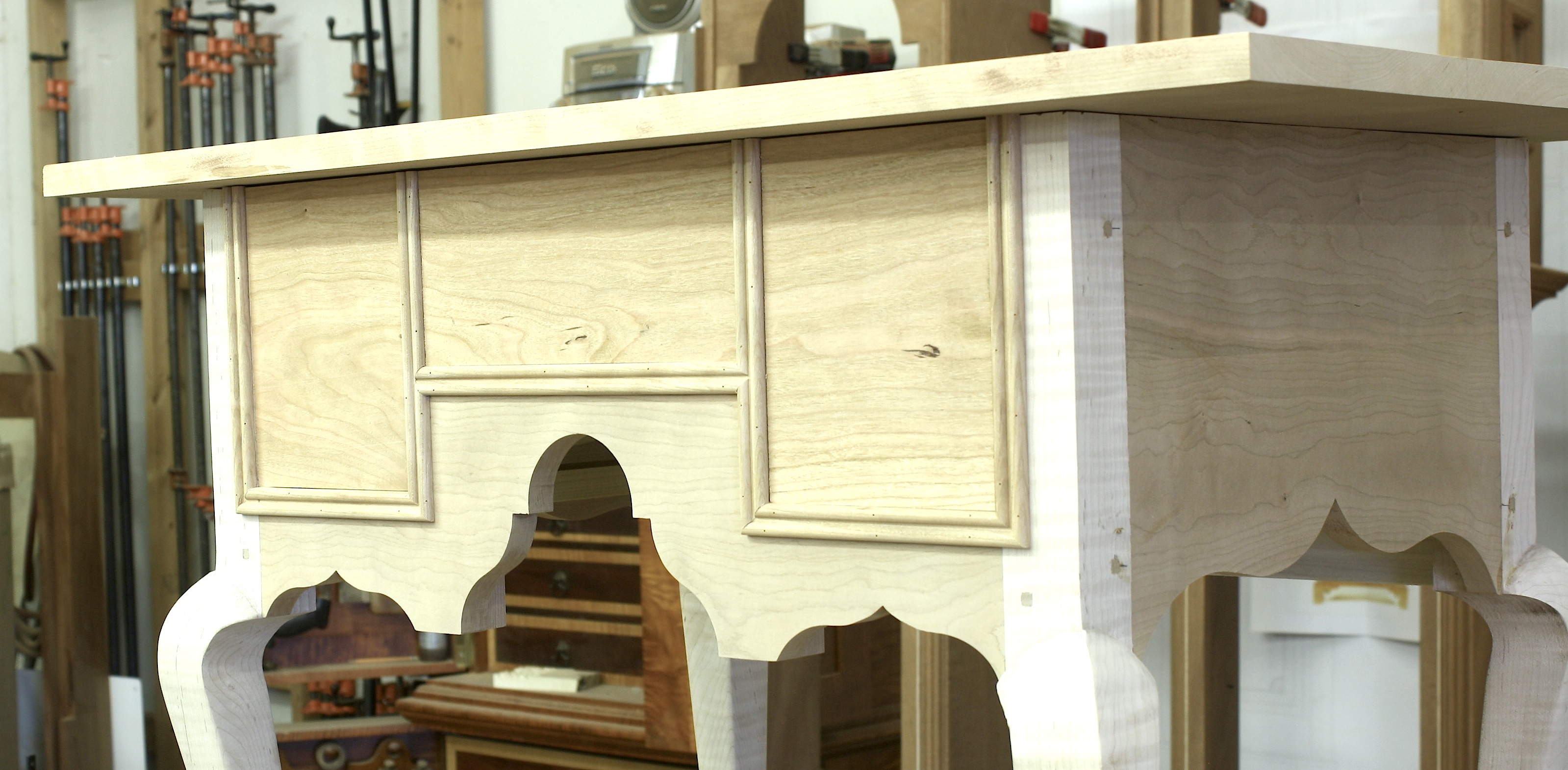
I settled on a small blackwood dot above each fan. To make the dots, I used a 3/8″ plug cutter then sliced the discs off using a handsaw – that way I could control the thickness of each disc. The recesses for the dots was nothing more than a shallow hole from a Forstner drill bit. Once the holes was cut, I dropped a bit of glue into the hole and set the disc in place. After the glue had enough time to dry and after I had cut, shaped and installed a simple handle in the lid portion of the box, I leveled the front of the box as shown in the opening photo.

I add a couple hinges during the week, and I hope to use rare-earth magnets to keep the box closed. After that, I’ll apply a few coats of my oil/varnish mixture and that should do it. If I missed anything that you’d like to know, please drop your question in the comment section below. I’ll get you a reply in short order.

Build Something Great!
Glen

2 Comments

Filed under Hand Tools, Inlay, Power Tools, Routers

Karens Inlaid Box (Part II)

IMG_1678When I returned to the shop this week, I took the clamps off the box and checked out the assembly. Things looked good, so I moved on. Step number one was to add a lid. Because I wanted to hide the lid’s appearance, I created a lip that was slightly less in thickness than the planned corner inlay. After sizing a piece of mahogany to that of the box, I used a two-step cut at the tablesaw to rabbet the piece. The lid was ready, so I glued it to the box.

IMG_1668As the glue dried on the lid, I found a scrap of tiger maple and milled the corner inlay material to size. Off the saw, I ran the 3/16″ piece through my spindle sander to bring them to perfectly square (5/32″) and to clean up any nasty burnt areas. The next step was to rabbet the box for all the corner work. Because the box was square, I could simply use a straight bit set up in my router table. (If any of the edges were rounded or curved, I would have needed a bearing-guided bit.) Set-up of the bit height and fence is critical; if I rabbeted too deep the inlay I made was once again scrap. To dial in the exact setting, I used a piece of the inlay as a guide as shown above.

IMG_1670When the glue was dry, it was off to the router table to trim the corners. I rabbeted only the four face corners at this time. The plan was to install the corners, then when the top edges were rabbeted, the installed pieces would be cut and the those inlays would terminate into the top edge inlay. Bring on the glue and blue tape. (I find blue tape invaluable when working with inlay.) I added a bit of glue into the rabbet, slipped in a piece of corner inlay then taped the thing in place as the glue dried.

IMG_1674To separate the top from the box, I used my table saw. Before making any cuts, I sliced a couple filler strips that are equal to the blade’s kerf. At the saw after trimming any extra lengths of corner inlay flush with the box top, I made two passes along the front and back of the box cutting through its walls. The filler strips were slipped into those cuts, I then added a clamp to keep the top and base in place as the next set of cuts freed the two sections. You can see the operation at the right, but you might also notice that I positioned my clamp in the wrong orientation. I could easily make the first end cut, but I had to add a clamp then remove the first clamp in order to make the second cut. (If I had just moved the clamp, the sections would not have moved, but the filler strips could have fell out causing more work.)

IMG_1677Once the top was off, I returned to the router set-up to run the rabbets for the four top edges and fit corner inlay to the cuts. These pieces required miters at the corners. I used my bench hook and my Dozuki saw to make the small miters. Once cut and fit, it’s back to the glue and blue tape. As the glue on the box top dried, I milled and installed bands around the base of the box – these piece were the same thickness as the corner inlay. I also fit and installed a band around the top edge of the box – these pieces were half the thickness of the corner inlay and a second band was applied to the bottom edge of the top. (When the box was joined and closed, the total thickness of the middle banding would equal that of the corner inlay thickness.) Each of these pieces were mitered at the corners. Everything was set aside to fully dry.

What’s left are the three fan inlays and to sand and finish the box. Oh yeah. I need hardware and a handle, too. Got to get creative for that.

Build Something Great!

Glen

Leave a comment

Filed under Hand Tools, Methods of Work, Routers

Different Blade Connection

6-Dr_Chest_Complete-1Wonder what blades are? It’s simple. In furniture speak, blades are another name for drawer dividers. As you probably know, there are many techniques and joinery methods to attach drawer blades to the case. The technique shown here is one that is not all that common, but it is found in antique furniture, namely the Moses Bayley high chest of drawers from Newberryport, Mass. (There is a fascinating bit of history surrounding the highboy; read more about it here.)

In the first issue of American Woodworker magazine under the complete guidance of F+W with me as the content director, I built a chest of drawers (shown above) using this blade connection technique – the issue should be available sometime in early June. (You and 100,000 of your closet friends should pick up a copy!)

B_SlotThe process is easy. While the connection could be done without plowing an 1/8″-deep groove, it’s easier to do so and the groove adds another detail to your work. Step #1 is to rout the groove – align a straightedge to your project, then run a router and 3/4″ top-mount bearing router bit along its length as the bearing rides your straightedge. The width of the groove has to match the thickness of your drawer blades.

Step #2 is to form the dovetail on the ends of your blades. The length of the dovetail – how high you need to raise your router bit – is equal to the thickness of the material remaining after the groove is cut. A_Dovetail
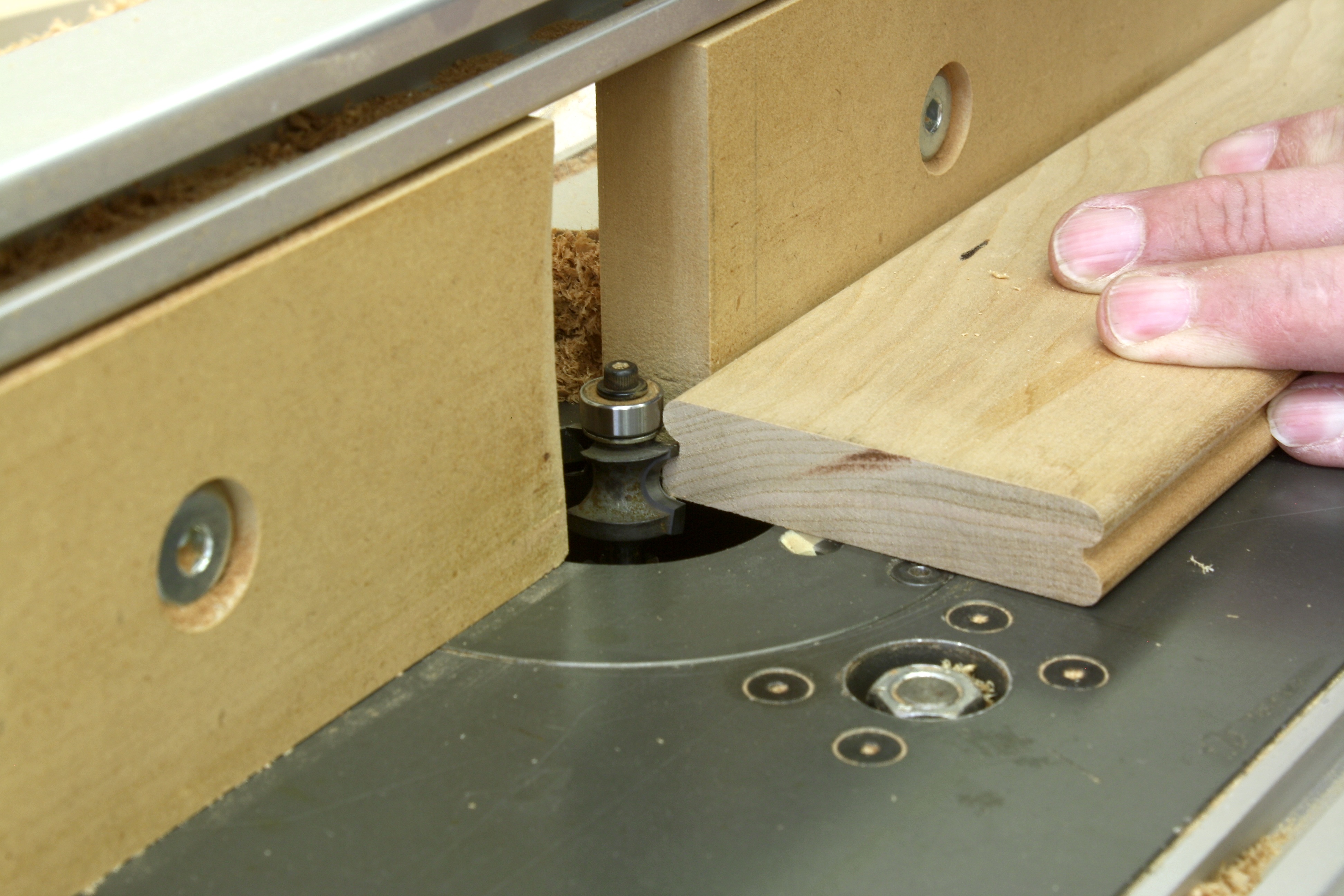
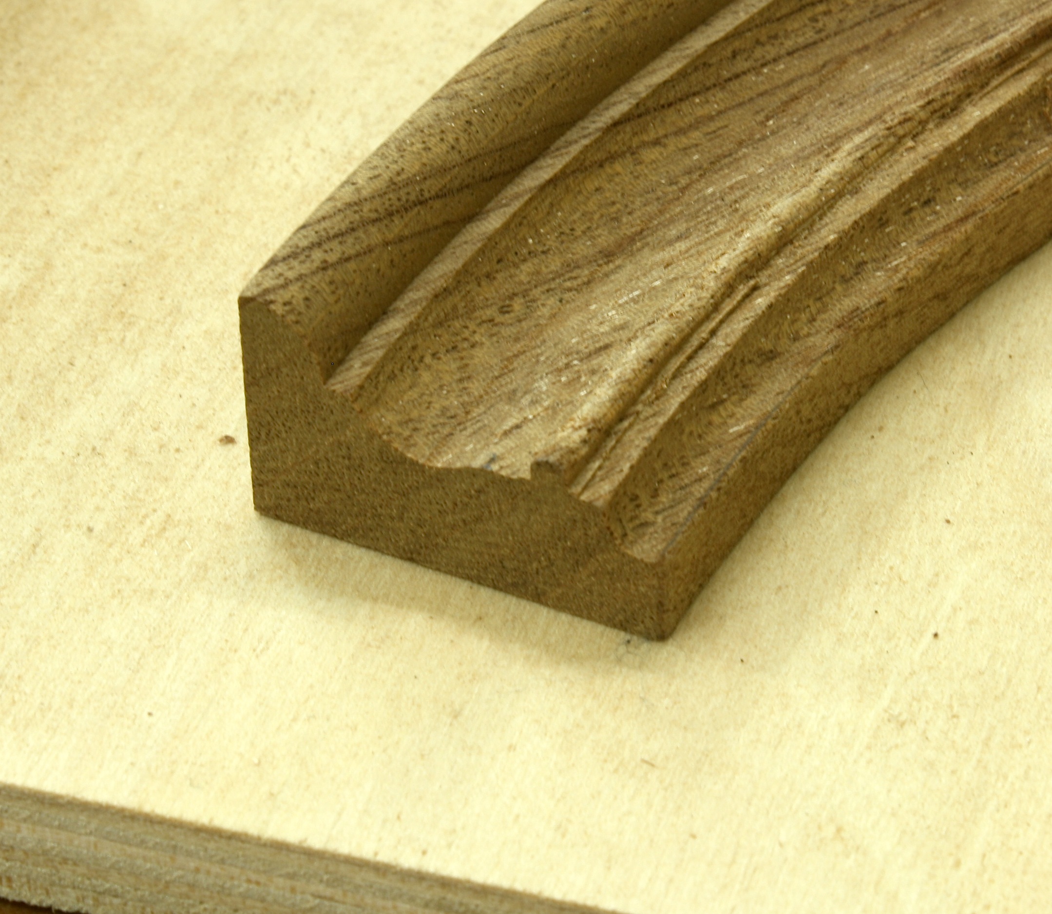
If you’re using 3/4″-thick material, after the 1/8″ groove you have 5/8″ of thickness remaining. For me this is a bit of work completed at the router table. Set the height of the bit then adjust the fence so its aligned with the router bit exactly at the table’s top edge. This takes advantage of the entire thickness of your blade – if you’re slightly thinner after your cut, that’s OK, but do not leave a flat on the edge of the dovetail. (Notice the solid push block used to guide the tall drawer divider through the cut.) After you have the dovetail ends created, cut away the back edge leaving a 1″-wide dovetail – trim the dovetail away flush with the square shoulder on your blade.

C_LayoutStep#3 is to transfer the dovetail profile onto your case side. As you can see in the photo, the blade slips into the groove and the trimmed dovetail sits tight to the case side. Using a sharp pencil, transfer the profile. Nothing fancy here. No special details to share. Simply install the blades into position then draw the lines. Bingo.

Step #4 is to square the layout lines down the case side 1″ (matching the dovetail width), then draw a straight line setting the bottom of the socket. D_Saw
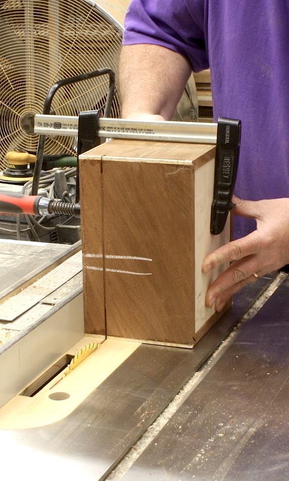
It’s time to define the socket. This is where your ability to saw comes into play. Cut the two sides of your layout down to the inch mark. Follow both lines as you saw. After you’ve established the socket’s outer edges, make a few additional saw cuts between the lines – the more kerfs you have, the easier the next couple steps become and the cleaner your socket will be to work.

Step#5 is to break out the thin pieces of wood that fill your socket. E_PareYou can jam a chisel into the slots, or if they’re thin enough, you can break the pieces out with your fingers. The neat things is that when they break – due to the grain orientation – the slivers break flush with the bottom edge of the socket. (Sometimes they do break slightly above the line.) With the pieces out of the way, pare the socket bottom so it’s smooth and level. Make sure the socket is level from outside to inside. And it wouldn’t hurt to slope a bit toward the inside – that guarantees you’ll have a tight fit on the exterior of your case.

The last step is to fit the blade’s dovetail into the socket. F_FitIf you’ve sawn to the layout lines and trimmed the socket even at the bottom, your blades should fit easily. Brush glue onto the dovetail and into the socket (the best glue surface is the flat-grain to flat-grain connection at the bottom of the socket), then drive the workpiece home. By the way, don’t forget to repeat these steps twice for each drawer blade or divider. Test-fits are terrible with only one socket cut.

I’m not going to show you a finished shot of the chest of drawers – for that you’re going to have to wait until the issue is sent – but I will show you a photo of the highboy mentioned above. In fact, if you’re so inclined to want to see this process in action, I have a full-length DVD on building the Moses Bayley chest. You can purchase a copy here.

Build Something Great!

Glen

G_MA High Chest

2 Comments

Filed under Antique Pieces, Hand Tools, Joinery, Methods of Work, Power Tools, Routers

Reeded Column Round-up

IMG_1455I’ve reached the ends of the reeded columns for my tall clock. Literally. The last step is to round the ends of each reed. I thought I might be able to speed this process along using a lathe to round the ends in one fell swoop, then just touch them with my carving gouge. That, however, was a waste of time – and one good column. Spinning the column at the lathe again meant that I needed to locate the centers, load the workpiece accurately and have it spin dead-on. Looking back, I should have known it wasn’t going to work. But sometimes I’m pig-headed and have to prove myself wrong before I turn to other methods. Boy was I proved wrong.

I then turned to my carving tools. There are eight column, each with 12 reeds. That’s a whopping 192 reeds that needed round ends. (That’s why I was looking for a speedier solution.) I matched the reed shape to my closest-sized carving gouge, which turned out to be a #9, 5mm tool.

The process is easy once you get started. The gouge is inverted on a reed, set close to the end then pivoted upward as the cut is made. It takes a couple of passes to get the end shaped as needed, and to keep the ends aligned with one another. The series of photos below show the actual movement. The opening photo shows three completed reeds.

IMG_1449IMG_1450IMG_1451IMG_1452

Of course, there was more work to do. Each of the reeds needed to be worked a little for a better rounded shape. (I should have set the scratch beader a bit deeper, but hindsight is, well you know.) Each end was shaped and each reed has been sanded smooth. I should wrap up the hood work this week. A few inlaid blocks is all that’s left. We’ll see.

Build Something Great!
Glen

Leave a comment

Filed under Hand Tools, Methods of Work, Tall Clock

Sometimes It’s Best to Scratch

IMG_1426After the holidays, I was back in the shop working to reed the columns for the Egerton tall clock. You all know that I’m more power based when I woodwork, so I first turned to my router and router table to form the reeds. I had a small router bit with a needle point (similar to the one shown below at right). I built a small carrier for the columns, installed the bit in my router table, adjusted the fence to cut at the center of each column then raised the bit ever-so-slightly Pointed Bituntil the two radii were just formed. I thought the cut was a bit deep, but the bigger problem was how to rotate and align for the next cut. Because I was working on the bottom edge, it was impossible to align the bit point to any layout lines. Scrap that idea.

My second power-tool effort was at my lathe. I have a jig built (shown at the right) that suspends my IMG_0311trim router at just the right height to allow a spinning bit to cut at the center on any turned stock. That jig setup, teamed with the indexing abilities of the lathe, suggested success. The bit I used, however, had a squared end (not a fine point) which resulted in a flat area between each reed that was unacceptable. And to use the bit consistently, I needed to run the bearings against the workpiece, and the cut was too deep, leaving the individual reeds too narrow and misshaped.

The only idea I had left was to scratch the design by hand. With eight columns to profile, that’s a lot of scratching. That’s why I looked to power tools from the outset.

IMG_1418The first step was to produce the scratch profile onto a blade, which in my case was an old, previously used scraper. I found this work best completed using files. There are times when you can drill out a pattern, then touch it up. But for this design, I went straight to a file. Using a square file, I cut notches into the blade to resemble a “w.” I found it easier to accurately form the notches using a square file than it was to use a round file to get straight to the radius design. As you work you make corrections to get the design just right.

With the notches cut and located, I switched to a round file IMG_1419(mine was a chainsaw file picked up at my hardware store). Fit into the notches, it was too simple to cut the design to round. Work one side, then move to the second. As this is done, make sure that the two rounded profiles stay tight to the center, and keep the point as small and sharp as possible – you don’t need a deep recess between each reed. One last adjustment to the profile is needed – remove the outside shoulders so the only bit being scratched is the recess and half of each radius design. (You can see the final design in the photo below.)

IMG_1425When I completed the design, I loaded the blade into a simple stock. I used two pieces of scrap through which I installed a couple of bolts and wing nuts. Slip the blade into position then tighten the wing nuts until the blade is secured. The carrier I built when attempting the router cut is what I used to hold the columns for scratching. To center the assembled scratch stock to the carrier, I added a couple of small blocks to the setup – #23-gauge pins did the job.

In the opening photo you can see how the jig is used. The blocks keep the scratch stock in line as the assembly is pulled and pushed back and forth until the design is formed. The blade hangs down far enough so the final depth is reached as the stock sits flat to the carrier frame. When one line is done, rotate the column and scratch a second. You can repeat this all the way around each column, but as Mike Siemsen of Green Lake Clock Company pointed out to me a while back, many of the columns found on antique clocks were not completely reeded. Because you cannot get your head between the hood and column, you cannot see those reeds. As a result, there are no reeds there. (In the past, if it was not seen, minimal time was spent making things look great.)

I have three columns ready to go, so I’m back in the shop scratch the remaining eight. Then I have to cut and fit each column to the capitals and hood. I’ll be busy for a while.

Build Something Great!

Glen

Leave a comment

Filed under Hand Tools, Jigs, Methods of Work, Tall Clock

Goose-neck Mouldings

Kasper Bonnet TopGoose-neck mouldings are, in my opinion, the great equalizer in any discussion of moulding planes or power tools for curved designs. Sure straight runs of moulding can be made using hollows and rounds, but the curved mouldings are a completely different animal. With goose-necks, you better be thinking kindly about a router, router table or shaper. And, you probably should have a selection of carving tools if your design has a rosette and doesn’t return on itself (as shown in the above photo).

#5024-01Of course, the Egerton clock has rosettes. This translates into more hand work using carving chisel. But the bulk of the waste is removed with power tools. You just need to find the correct profile, and that can be tricky as you flip and turn the profile looking for a match, especially if you’re using bearing mounted router bits. (I’m tossing out shaper work, because most woodworkers are not working with a shaper – router tables have all but replaced the shaper in home shops.)

The best way to run these profiles using a router is with the face of the goose-neck moulding facing up. To do that you need an over-arm pin router setup, or you need to create a method to hold your router above the workpiece as you guide the cut, as shown to the left. Router_JigThis setup uses the guide-fence holes and scrap pieces to raise the router cut abilities. The setup is easy to duplicate, but using the arrangement is not that simple. You need to accurately guide the router along the curved lines of the goose-neck while holding things at 90° to the workpiece. Slow and steady wins the race, but even then you have clean-up work to do. It is much better if you can use bearing-mounted router bits. To do that in this scenario, I had to run at my router table, keeping the face of the mouldings against the table.

The problem with bearing-mounted router bits is reach. On wide goose-neck mouldings, you often cannot reach back into the profile enough to make things work. IMG_1399On the Egerton moulding, though, that’s not a problem because it’s only 7/8″ wide. I was able to use the bearings on my router bits of choice to get the job done, so the first bit used was a cove design for raised panels. That router bit allowed me to reach back 3/4″ of the 7/8″ needed – that left an 1/8″ of flat at the top edge of my profile. On the straight runs, cut from end to end. On the curved work, you need to stop just short of the rosette area.

The second profile I used was a simple 1/4″ round-over bit, but I switched out the normal bearing to use one that was a 1/8″ smaller in diameter. IMG_1401That change moved the round-over profile in slightly on the workpiece. Height adjustments need to be accurate. Because I was looking to flow the second profile into the larger cove cut, I found it best to sneak up on the final setting. I could have stopped at this point, but the square edge left after the second router cut was smaller than what I saw on the original clock profile. I wanted more.

Deciding to make the last router-bit cut added the needed square-edge to my profile, but it also caused more work after routing work was complete. IMG_1403To achieve an additional 1/16″ of square edge for an 1/8″ total, I used a rabbet bit to push the design up into the moulding. That cut removed a lot of the round-over profile, but that would be easy to replace with carving tools, and the extra square edge made the design of my goose-neck more in line with the original.

To complete the mouldings, both the curved and straight pieces, I use a couple carving gouges to re-round the profile. Work on the straight pieces was easy. I found and carved with the grain direction. On the curved pieces, carving required that I move in different directions due to the grain changing as the curves undulated. Even with that need, the work was not difficult.

Next week I’ll show the completed and installed goose-neck moulding with the carved rosettes in place. I’m getting close to finished.

Build Something Great!
Glen


1 Comment

Filed under Hand Tools, Jigs, Methods of Work, Power Tools, Routers, Tall Clock

Egerton Moulding Install

I promised last week to show you the moulding installation. But if you stopped by, you found that I was unable to post. So as promised, here is the technique I use to cut, fit and install the lower moulding on the tall clock.

Layout is the important step. First position the arched moulding to the hood. After it’s in position draw a line along the back or top edge. IMG_1365Make the line run the entire length of the moulding, or at least indicate where it crosses the inlay at the center and the lower 2″ at the hood’s base. The second step is to lay in the straight line to indicate where the moulding runs along the base – show the area that fits between the arched moulding and the hood’s return. To obtain the angle needed to fit the two pieces (arched and short straight) draw a line from the two corners as shown in the photo above.

Moulding Marking

To reveal the cut lines on the moulding, slide the arched piece back into position then use a couple of spring clamps to keep it in place. On the top edge of the moulding, mark where the lines intersect – the intersection of the arched and straight, as well as where the arched crosses the inlay should be marked. Repeat the steps to mark the two points on the inside edges of the arched moulding. Both steps are shown above.

On the back face of the moulding, make a couple of tick marks that show the two points then use a rule or straightedge to draw the line from mark to mark. Strike the lines at the two layout points. IMG_1374I also square the lines down the back edge of the mouldings to provide two points of reference as I cut. Because the moulding is arched, a couple of spring clamps will hold the piece secure as you cut. The easiest way to cut the lines is to grab your handsaw and make the cuts. I like a Japanese saw for these cuts because the finer teeth are easier to start, and glide through the cut better. This saw is from Lee Valley (link). Make the cuts while watching both lines – it’s the same as when cutting dovetails. After the arched moulding is cut (touch-up the cut with a small plane if you’re off your layout line), reposition the arched moulding to the hood.

The next step is to cut and fit the short, straight moulding at the base. You can repeat the same procedure to cut this piece; layout the two points, IMG_1375strike your line then saw the cut by hand. But for this cut – because it is a straight piece of stock – I work at my miter saw. I simply guess the angle then make a couple of cuts to hone-in on the final angle. You could, of course, use a bevel gauge to setup the correct miter. Even using a bevel gauge, I find myself fine-tuning the cut, so I go right to the saw. Make sure your fit is tight and that the moulding profiles align. You will have a small amount of work to do to bring the two profiles to match, but the work should be minimal.

For me the tricky part of this installation is the next step. On the top edge of the straight moulding, mark the start of the 45° bevel, and indicate the direction of the bevel. IMG_1377(That’s where I sometimes have problems.) It’s easy to get things turned around as you move to make the cut. I, again, use my miter saw. This is also a straight piece of stock and easily set and cut at the miter saw. Because it is a small piece, you may not feel comfortable at a power saw. If that’s the case, use your handsaw and a bench hook to do the job.

The last piece – on this first side – is the return. It’s a simple 45° cut at the front with a 90° cut at the rear. With all the parts cut and fit, turn your attention to the second run of mouldings. IMG_1378The process is the identical, but the angles are reversed. When both sides of the mouldings are fit, use spring clamps to hold a run in position as you prepare to attach the pieces to the hood. Working with the arched piece of moulding, add a thin bead of glue to the back face, then position it to the hood and to the short straight piece that is clamped in place. A few #23-gauge pins hold everything as t he glue sets. Work from there to the return, then repeat the same steps to install the second run of mouldings.

Build Something Great!

Glen

Leave a comment

Filed under Hand Tools, Methods of Work, Power Tools, Tall Clock

To Scratch or Not

IMG_1276In a blended woodworking shop – how any woodworking shop should be set up – you make choices about when hand work is appropriate and when it makes better sense to use power tools. That decision should not necessarily be guided by a passion for any particular method or tool; as woodworkers, we face this whenever we hope to be productive in our shops.

In a post a few weeks back (read it here), I wrote about how easy it was to make a simple scratch beader (scratch stock) to profile the arched moldings on the Egerton clock hood. With that project on hold while I build a cover piece for an upcoming issue of Popular Woodworking Magazine, I faced a similar choice as I made drawer molding for the transitional lowboy. (If you’re a furniture purist, don’t tell me I’m not suppose to use the term transitional – that best describes the project on which I’m working.) IMG_1278The moldings are a double-bead design that signifies later William & Mary period work. And the fact that the lowboy has cabriole legs (Queen Anne) also indicates a transitional build.

I decided to make another simple beader, but this time the tool was a bit more involved. Not only did I drill the holes and sand the profile, I needed to set the blade into a handle to register the molding with each pass. Even with the handle added, making the tool was too easy.

In order to use the scratch beader, I ran a slot down the middle of my stock using a slot cutter setup in my router table. At the bench with the stock set in my vise, I scratched the double-bead profile into the edge. At my table saw, I set the cut for 1/4″ then ripped the first piece of molding free. Everything worked, but the process to get six pieces of molding was too long.

IMG_1270Using my router table with a 1/4″ corner-beading router bit installed, I ran a pass to form the bead, flipped the stock to rout a bead at the opposite face, then ripped the molding at my table saw. I was easily convinced that this was the process I would use. But what guided my decision? First there was the ease of the entire process. Router cut was far easier and quicker than walking through the steps needed to do the work by hand. Also, the pattern or profile was consistent with each piece of molding cut. This is important because there are a couple of places, as you can see in the opening photo, where these molding pieces meet and intersect with one another – matching profiles are easier to fit and blend (hand-cut work can require further shaping and sanding).

What did I give up? The original molding profile I was after was a 3/16″ bead at each edge of the 5/8″-wide stock, with a 1/4″ of flat between the two beads. What I made using power tools was a 1/4″ bead at both edges with an 1/8″ flat – not the same design. I could have found and purchased a 3/16″ corner-beading router bit, but I didn’t think it was that important. If this was a customer-purchased lowboy, I would have built the piece with the 3/16″ beads. But given the fact that it is a piece for me – as most of the projects you build are for you – I opted to be more productive in my shop.

Build Something Great!

Glen

3 Comments

Filed under Hand Tools, Jigs, Methods of Work, Power Tools, Routers

My Night Cap

#5024-01There are times when I need to get into the shop just to have fun. That time generally rejuvenates me so I can get back to my projects with a renewed vigor. If that fun time also happens to be something I need for one of my projects, I consider that a bonus. This week was a bonus. I needed to make a piece of inlay for the tall clocks. In the photo you can see, on the original Egerton clock, the piece of inlay I needed to make, the Night Cap perched on the post. This post is more pictorial that text filled, but you know what is said about a photo.

Step one was to develop a pattern for the inlay. I could have drawn the design free-hand, but it’s easier to pull the image into SketchUp and trace over the lines. After I had the plan, I spray-glued the images onto a piece of scrap holly and cut the pieces at my band saw.

B_IMG_1152

When I had the pieces cut out, I smoothed the edges as best I could using a disc sander and fine rasp before moving on. I also made sure the two pieces fit together nicely. I wasn’t worried about a super-tight fit because the separation would better show the delineation between the two pieces.

C_IMG_1154

Using a bench hook, I sawed the pieces into thin, usable slices. I like my Japanese saw for this cut. It’s thinner kerf saves material, and the small, finer teeth make the task easier.

D_IMG_1155

Sand-shading is great. There are few techniques as simple as this. And the results add a crap-load to the overall look of your work. The only pieces in this design that get shading are the small ovals.

F_IMG_1160

To inlay the pieces into my stock, I have to excavate the waste. This is really where a router becomes valuable. I positioned the pieces to my backer, then carefully traced around each piece with a sharp pencil. With a 1/16″ straight bit loaded into the tool, I set the depth of cut then hogged out as close to the lines as possible.

G_IMG_1163

Afterward, I used a small carving gouge to tweak the inlay area to my layout lines. I tested the fit of my inlay to the excavated hole, then trimmed any needed spots. (I want a tight fit, but not so tight as to break my inlay.)

H_IMG_1161

With the areas cut away and trimmed to an exacting fit, I added glue into the recess and hammered the inlay pieces into place.

I_IMG_1162

The rod for the Night Cap holder couldn’t be easier. I used the same 1/16″-diameter bit, set the workpiece flush with the edge of my bench then used a guide fence on the router to cut the line. The rounded ends from the router bit worked great against the small ovals to complete the design. A piece of string was cut to fit, a small amount of glue was injected then I hammered into the recess.

J_IMG_1164

At my table saw, I set the fence and raised the blade to trim the edges for more string banding. The pieces were cut to size and I mitered the corners using the reflection in the back of my chisel to set the angle – too easy. Glue to hold and blue tape as a clamp, then let it dry.

K_IMG_1165

With the glue dry, I sanded each face – I built two of the pieces – then cleaned up the edges with my block plane. Before I install these on the clock hood, I’ll thin the assembly somewhat. The two pieces are a bit different. So, are the results perfect? No way, I wouldn’t expect that. Was it fun to do? Hell yes. Every once in  while you need to get into the shop to just have fun.

A_IMG_1182

Build Something Great!

Glen

7 Comments

Filed under Design, Hand Tools, Inlay, Methods of Work, Power Tools, Routers, Shop Tips, Tall Clock

… Just Scratch It

IMG_1141Last week I worked on the arched moldings for my clock and left you with going back into the shop to used different setups and a new design. It worked. Kind of. It turns out that I did use my Micro Fence circle-cutting jig, but I had to also use my shop-made jig, too. The Micro Fence system did not allow me to get as small as I needed to make my moldings. The opening photo is that of the second profile as it came off the router. (You can enlarge the photos if you click on them.)

This week I began from the profiled arched moldings.IMG_1144 Three things to do: cut the arched pieces from the stock, make a set of straight moldings to match what I had in the arched set and work the small bead of the moldings. At the band saw, I cut away the waste to free the almost completed arched moldings. A quick trip to my disc sander (the outside edge) and my spindle sander for the inside edge and I was ready to begin matching the profile on some straight stock.

One of the ends of each of my four arched moldings is square cut – IMG_1147the ends that met in the middle of my setup. Using that end, I worked through the profile using the same router bits used to make the arched pieces. I had to set the depth of cut and the fence location to accurately match the design. It took about two hours to create a matching design on my straight stock. The last cut was the 1/4″ round-nose bit profile. With its work complete, I could rip the molding pieces free.

The last step was to create the 1/8″ bead on each of the sticks of molding. IMG_1150My first thought was to carve the pieces. I grabbed a small, bent-back carving gouge from the roll and got ready. After a couple minutes, I knew this was not the answer. Plan B – which should have been Plan A in retrospect – was to make a scraper for the task. Simple enough. I drilled an 1/8″ hole near the edge of one of my scraper blades, then ground it (sanded it with my spindle sander) so only half the profile showed. Work began on a straight piece of stock. Scrape. Scrape. Scrape. Done. It was too easy. The second, third and fourth pieces of straight molding went just as quick. But what about the arched pieces? I clamped one in my vise and went at it. The results were just as great and just as quick. The finished molding is shown above right, and the process is shown below. (The inset photo is the bead scraper.)

Combined

If you run into this need, make a scratch beader your Plan A. It’s way easy to do. And it works.

Build Something Great!

Glen

1 Comment

Filed under Hand Tools, Methods of Work, Shop Tips, Tall Clock