The LVL desk build continued with the legs. I milled 8/4 material, then joined two pieces to form four 3-1/2″-square legs. Square wouldn’t do, so we decided to taper the 28″ lengths over 24-1/2″, leaving a bit of square at the top. Tapering legs is best done at a jointer, if you ask me. As long as you hit your layout lines, you can nail each leg so that they are all tapered exactly. It took only minutes to taper all 16 sides.
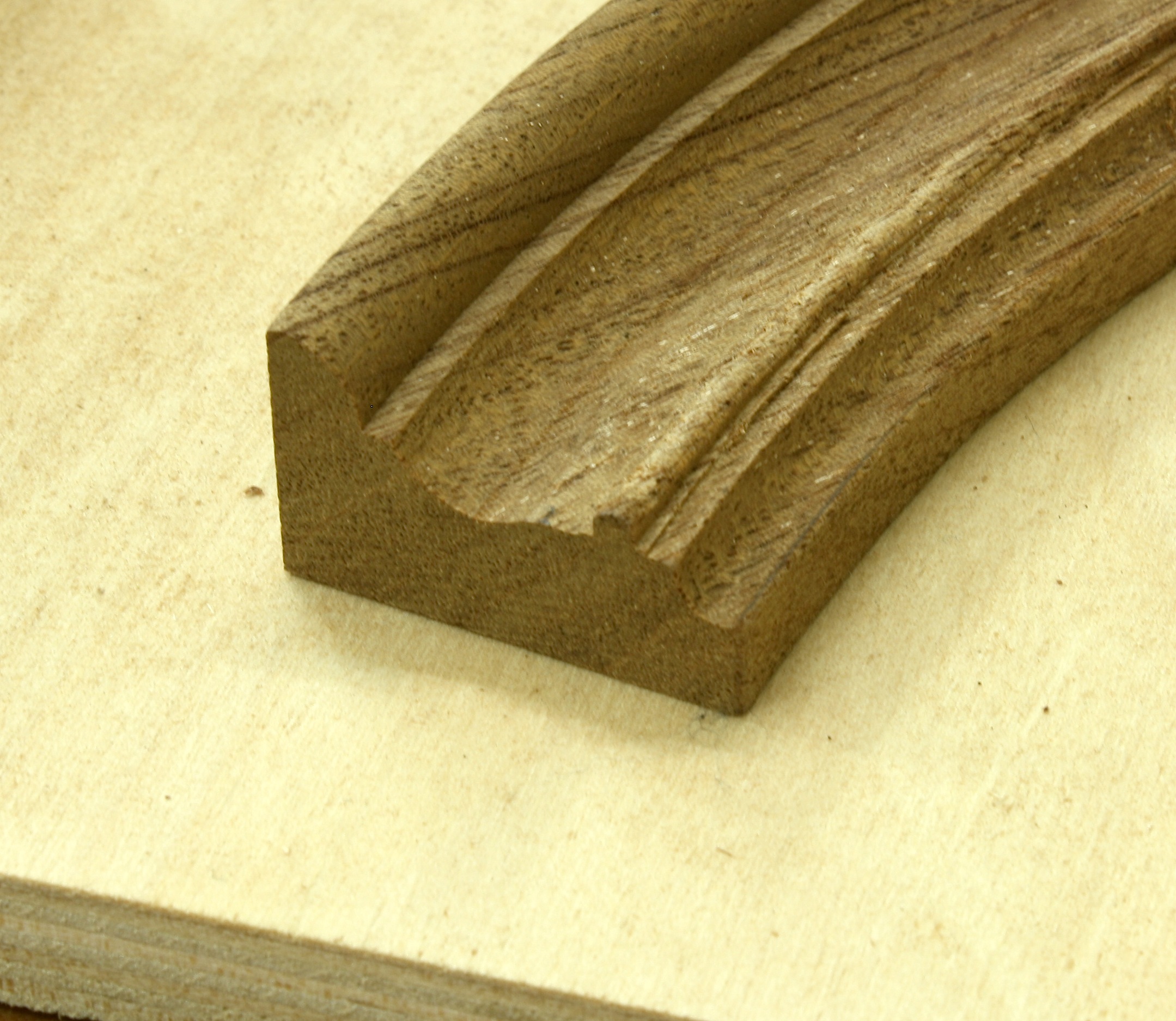
Still, the legs didn’t have the right look, so we decided to chamfer the corners. But how do you stop the chamfer at the perfect location? You don’t. We trimmed the corners along the legs entire length; that left the square portion at the top end tapering out of the cut made at the router table.
 To join the legs to the top, we went with a simple idea – dowels. If we would thought of this at the beginning, we could have drilled the leg ends while the blanks were still square. But, of course, we didn’t, so the set-up was a bit more involved. I rotated the table on my drill press, clamped a straightedge in position then centered the 1-1/4″-diameter bit in the leg, which was clamped to the straightedge. (Told you it was more involved.) Holes were drilled about 1-1/2″ deep because the arm of the press came down onto the rotated table to stop the cut. That wasn’t enough of a hole in my opinion. Afterward, each hole was set another 1-1/2″ in depth, and dowels were glued in.
For each leg to fit tight and flush with the bottom surface of the tabletop, it was imperative that the 1-1/4″-diameter holes drilled through the top be square to the large flat surface.  There’s no better tool than a router for this work. I don’t, however, have a router bit that diameter, so there was no way to plunge the holes as you would when knocking out adjustable shelf pins. The next idea worked perfectly. drill through the top in the correct location using a smaller diameter drill bit (in this case I used 3/4″), then enlarge the hole using a top-mount pattern bit. All that’s needed is a scrap piece of plywood with a hole drilled exactly to size; that’s easy with the drill bit already in the press.
 To use the jig, clamp the plywood piece in position on the table’s top over the previously drilled hole, slip the router setup into the hole with the bit’s bearing riding along the plywood cutout and rout a perfect matching-size hole in the top. To get through the entire 2″ of top, we had to remove the plywood and repeat the steps using the trimmed portion of the hole as a guide. Easy, peasy!
 With the holes drilled and the dowels sawn for wedges, we slipped the legs into the top, spilled a little glue into the sliced dowel then drove walnut wedges to bring everything tight. The final look with the dowels and wedges trimmed look good. Plus, there’s no wobble in the table, especially after the glue dried.
Build Something Great!
Glen