Category Archives: Methods of Work

Best Tool for the Job

Something that I preach is that we woodworkers should use the best tool for the job. It that’s a table saw, jointer or big-honkin router, so be it. It the best tool is a handplane, egg-beater drill or sharp chisel, go for it. Mitersaw_cutTo be wholly dedicated to one woodworking discipline while ruling out others is nuts.

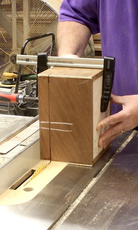
The story I like to tell is a tale on myself. When I built the Baltimore Card Table article for Popular Woodworking Magazine, I was more dedicated to power tools even though I used hand tools. In one of the early steps of the build, I needed to trim the ends of the brick-laid apron. I spent 20 minutes or more setting up the cut at my miter saw. Of course, the cut was square and right. (See the image from the article above.)

Years later, after hand tools began to play a bigger role in my day-to-day woodworking, I taught how to build that table at a woodworking school. When the time came to trim the apron, I grabbed my pencil and square, laid in the lines then made the cut using a hand saw. Of course, the cut was square and right. The difference was that I did not spend 20 minutes setting up the cut.

What’s important is to choose and use the best tool for the job.

In the photo below, I guess the tool would be classified as a hand tool. I  know, however, that it is the best tool for the job. Why? No only does this tool make spreading the oil/varnish mix quick to accomplish and easier to direct finish were it’s needed, the process also warms the oil ever so slightly to better allow mixture to soak into the surface.

OV_LVL_1

Build Something Great!

Glen

8 Comments

Filed under Finish Techniques, Methods of Work, Shop Tips, Shop Tool

Always Something to Learn

IMG_1944In woodworking, one of the most satisfying things is that you never know it all. Everyday there is something knew to learn. That’s one of the things that keeps me looking and listening and trying new ideas. In the left-hand photo, you see how I’ve set up to bend stringing since I first began working with the material. I grabbed a length of pipe in Vise-grips, clamped it into my bench vise, heated the pipe and bent the stringing over the pipe using a metal-strap backer. If you look close, you see a nail set slipped between the grips and vise. I sometimes found that downward pressure as the bend was taking place could cause the setup to move in the vise, and that’s not a good thing to have happen. The nail set stopped that.

As I’ve demonstrated this technique to different woodworking groups, I’ve had occasion to see a few interesting string-bending setups, including  a massive three-pipe selection that bolted to a workbench and allowed a constant flame to keep the pipe at the correct temperature for bending – whatever that is. I’ve also been asked so many times about using a heating iron as does Steve Latta; sorry Steve, that’s way too slow.

I did, however, learn a new setup while teaching my session at Woodworking in America this past weekend (the reason there was no post on this blog last Sunday). I traveled to Winston-Salem, N.C. without my Vise-grips and nail set. When it came time to demonstrate the technique, I was at a loss. Until, that is, I grabbed the F-style clamp I tossed in the conglomerate of stuff I’d taken along. With the length of pipe secure in the clamp, I set it into the bench vise with the handle resting against the top of the vise. No amount of downward force would cause the setup to move. And as long as you remove any plastic fittings from the clamp, heat from my torch was not a worry. It worked great.

IMG_1943There’s always something new to learn in woodworking.

Build Something Great!

Glen

3 Comments

Filed under Back to Basics, Inlay, Jigs, Methods of Work, Shop Tips

Table Legs & Terrific Technique

IMG_1883The LVL desk build continued with the legs. I milled 8/4 material, then joined two pieces to form four 3-1/2″-square legs. Square wouldn’t do, so we decided to taper the 28″ lengths over 24-1/2″, leaving a bit of square at the top. Tapering legs is best done at a jointer, if you ask me. As long as you hit your layout lines, you can nail each leg so that they are all tapered exactly. It took only minutes to taper all 16 sides.

Still, the legs didn’t have the right look, so we decided to chamfer the corners. But how do you stop the chamfer at the perfect location? You don’t. We trimmed the corners along the legs entire length; that left the square portion at the top end tapering out of the cut made at the router table.

IMG_1885To join the legs to the top, we went with a simple idea – dowels. If we would thought of this at the beginning, we could have drilled the leg ends while the blanks were still square. But, of course, we didn’t, so the set-up was a bit more involved. I rotated the table on my drill press, clamped a straightedge in position then centered the 1-1/4″-diameter bit in the leg, which was clamped to the straightedge. (Told you it was more involved.) Holes were drilled about 1-1/2″ deep because the arm of the press came down onto the rotated table to stop the cut. That wasn’t enough of a hole in my opinion. Afterward, each hole was set another 1-1/2″ in depth, and dowels were glued in.

For each leg to fit tight and flush with the bottom surface of the tabletop, it was imperative that the 1-1/4″-diameter holes drilled through the top be square to the large flat surface. IMG_1892There’s no better tool than a router for this work. I don’t, however, have a router bit that diameter, so there was no way to plunge the holes as you would when knocking out adjustable shelf pins. The next idea worked perfectly. drill through the top in the correct location using a smaller diameter drill bit (in this case I used 3/4″), then enlarge the hole using a top-mount pattern bit. All that’s needed is a scrap piece of plywood with a hole drilled exactly to size; that’s easy with the drill bit already in the press.

IMG_1891To use the jig, clamp the plywood piece in position on the table’s top over the previously drilled hole, slip the router setup into the hole with the bit’s bearing riding along the plywood cutout and rout a perfect matching-size hole in the top. To get through the entire 2″ of top, we had to remove the plywood and repeat the steps using the trimmed portion of the hole as a guide. Easy, peasy!

IMG_1897With the holes drilled and the dowels sawn for wedges, we slipped the legs into the top, spilled a little glue into the sliced dowel then drove walnut wedges to bring everything tight. The final look with the dowels and wedges trimmed look good. Plus, there’s no wobble in the table, especially after the glue dried.

Build Something Great!

Glen

Leave a comment

Filed under Design, Desk Build, Jigs, Joinery, Methods of Work, Shop Tips

LVL Desk in a Weekend

Steve's deskIt’s a holiday weekend. Yeah. I have an extra day in the shop on Monday that I intend to fill building a quick desk with my younger brother. He’s looking for something a bit toward contemporary and I’ve sold him on using LVL (Laminated Veneer Lumber) for the top with legs that are simple to make; he wants inexpensive and quick. The most time spent – at least I hope it takes longer than other parts – is time building a pencil drawer.

I took two hours to rip, square and assemble the pieces of LVL for the top one night after work. That includes time spent watching glue dry. The process is easy. Here are the steps in case you want to play along (or build something similar down the road).

2M4A2152I began with two LVL beams that were 1-3/4″ x 11-7/8″ x 10′-0″. After chopping the beams in half lengthwise, I set up at the table saw to rip each piece to 2-1/8″. Of course, one edge was ran over the jointer to give me a square edge to start. Using a 50-tooth combination blade, LVL cuts easy. The beams I purchased had a bluish painted surface, as you can see in the photo. That worried me little after making the jointer pass. Then after ripping the pieces and turning them on edge, you begin to see the final surface. To make up the 30″ in width needed to the desk, I ripped all four half beams, which produced 20 strips that were 1-3/4″ x 2-1/8″ x 60″+.

2M4A2153From the table saw, I returned to the jointer to true one of the two yet-painted edges to provide a solid glue surface. A single pass flattened all but two of the pieces. Those two pieces were areas where the lamination overlapped causing a bump in the face. I ran them a second time in order to achieve a flat face. You still see bluish paint in the left-hand photo because only one face has been flattened (all faces run over the jointer knives are downward facing, waiting for the planer.

2M4A2156A ride through the planer was so easy. All I needed was to flatten the second face for glue. The planer I used is setup with a spiral cutterhead. Even though there were no problems with the three-knife arrangement at the jointer, the planer surface was smoother. (This is why, when asked, I suggest that the planer have the spiral cutter, but it’s not that important on your jointer – the jointer is seldom the last surface of your work.) The first pass was great except for, you guessed it, the two pieces that needed the extra pass at the jointer. When those two were feed through the planer, the final surface was untouched in a couple places. A send pass through the planer was required, but only for those two pieces.

To my surprise, the most difficult process in assembling the two planks for the top was the glue-up stage. Spreading glue on the 19 pieces (yep, I had one strip left over after attaining the 30″ width) was a pain. 2M4A2159I decided to lay the strips out as if I were gluing panels for a case side. With the finished face up, I then rotated each piece to a glue face. With the pack tight together, I squeezed glue up and down the face leaving small lines covering the surface. I spread the glue using a thin scrap of wood. Scraping along the length was no good, but across the pieces worked like a charm. With one side gooey, I flipped the strips abd slathered up the second side. I was amazed at how sticky the pieces were as I tried to align the ends – I needed a mallet to move the individual pieces. Than goodness I assembled the 19 pieces in two separate groups. When finished, I added clamps and let the half-tops set. All in all, I used almost 3/4 of a quart of glue.

Out of the clamps in 45 minutes and all that was left was to clean the squeeze-out off and make a pass through the planer to level the two surfaces. When slid together – I still need to assemble the two halves – you get a good idea of how the top looks. My guess is it’s even better when a bit of finish is applied. Next week I’ll walk through the legs. Get it?

Build Something Great!

Glen

2M4A2161(1)

2 Comments

Filed under Desk Build, Methods of Work, Power Tools, Shop Tips

Best Glass Cleaner

IMG_1878Here’s a quick tip to clean glass panes or windows. Forget Windex Glass Cleaner. Forget those local community car washes that use newspaper to clean car windows. The best way to clean glass is with – wait for it – steel wool. That’s right steel wool. There’s no need for any liquid cleaner, but you have to use the right steel wool. You should use #0000 (four aught) steel wool.

I learned this tip from a friend years back. He was in the automotive repair and body shop business and was forever cleaning windows. At first, I thought he was pulling my leg (that’s Midwestern for joshing me, kidding me or otherwise telling me stories). As soon as I got back to the shop, however, I gave it a try. The results are great. I never turned back to any other method for cleaning my glass windows. Give it a try on your home windows, too. But make sure you’re not scrubbing any UV film coverings.

Build Something Great!

Glen

1 Comment

Filed under Back to Basics, Methods of Work, Shop Tips

Four-squared Boards

2M4A2095I needed a single board for a project that I’m building in an upcoming issue of Popular Woodworking Magazine. The only surface I need to look good is the front edge which faces the front of my cabinet. With no milled lumber available other than a few natural-edge cutoffs, I laid a straightedge on two of the cutoffs to remove the natural edges, made cuts at a band saw, jointed the edges and glued the two boards together to make one. A great method to stretch lumber on a project.

As I assembled the pieces, I thought back to classes in which I’ve taught woodworkers proper milling techniques using machines. Step one is to flatten a face. In my system, step two is to use a thickness planer to create a parallel face. For some woodworkers, step two is to square one of the edges while at a jointer, but I disagree. If you square an edge, does that edge remain square as you flatten the second face, especially while flipping the board end-for-end during the milling process to keep the exposed surfaces at equal moisture content? There’s a chance that it doesn’t – if your board rides up on an elevated edge of the planer bed, or if a small chunk finds its way under one of the corners as you send the piece through the planer, you could change the squareness of that edge of the workpiece. That makes step three, for me, to then create an edge that is square to both faces. It’s at this point that I often run crossways of students in the class.

Many woodworkers feel that it’s necessary (step four) that you rip the board at the table saw. Is it? The answer is that it depends. If you’re simply joining two or more boards in a panel glue-up, it’s not important that the boards are ripped into a four-square configuration. Why waste the wood. Make your step four at the jointer. In fact, one of the best techniques for hiding seams when assembling panels is to cut a board for a better grain match, which removes the four-square measurements from your board. If however, you’re preparing a board for use in your project, then make your step four at a table saw. You need to think through operations and not simply be guided by a set of rules. We all know that rules are to be broken.

If you’re preparing your lumber using handplanes, you need to go about the work differently. You also need to answer a question for me – what the hell is wrong with you? Milling lumber is grunt work. Use a machine for the grunt work and use your handplanes for finish work. C’mon man!

Build Something Great!

Glen

3 Comments

Filed under Back to Basics, Methods of Work

Hole in the Round

IMG_1867I learned this trick way back when I transformed countless wooden knobs into cupboard turns. I needed to drill the rounded portion or tenon of the knob – the part that generally was glued into the door or drawer – so I could insert a short section of dowel that would extend through the door. That dowel would have a wooden finger attached that would turn down onto a small wedge attached to the backside of the door. I could have simply purchased the turns, but the knob design seldom matched the other wooden knobs used on the piece.

Today, while using more brass than wood for pulls, knobs and turns, I use the technique only sparingly. But it’s a great technique when you need it.

IMG_1868Begin by drilling a hole into a scrap that is sized to the diameter of the rounded object; generally that would be the knob tenon when making a cupboard turn. In this case, I’m drilling a hole in the center of a dowel, so in my example, I’m drilling the diameter of the dowel (shown at right). Drill the hole deep enough to allow the base of the knob, if that’s what you’re drilling, to sit flat against the scrap. (You should do this with a drill press to make sure the holes are straight and true.)

Change drill bits to the diameter of you’re new hole, and drill clear through the scrap using the center of the first hole as a guide to align the second hole. The idea is that the first hole holds the piece to be drilled in place and the second hole locates the exact point of the new hole. To put this in terms of drilling out for cupboard turns, the knobs would have a 1/2″-diameter tenon into which I would fit a 7/16″-diameter post. There was little room for anything but exact alignment.

IMG_1865To use the setup, insert the tenon, or short piece of dowel in this case, into the appropriate diameter hole, align the drill bit with the second diameter hole (as shown at the left) and drill down. It’s that simple. Plus, every time you use the jig, the results are the same (as shown in the opening photo). And it doesn’t matter what diameters you use, as long as the second hole is smaller.

Put this trick into your pocket. Some day it will come in handy.

Build Something Great!

Glen

4 Comments

Filed under Jigs, Methods of Work, Shop Tips

Confidence is Key

Cherry Highboy copyA show about stained glass made my dovetails better. Yes, it’s true. I’ve told the story many times, but I don’t recall if I’ve written it in this blog. Here’s the abbreviated version. I was deep into watching a TV show about stained glass. As I watched, I was amazed at how easy stained-glass makers cut and broke the glass they used. Grab a good-quality glass cutter, etch the outline of what they wanted then snap the piece free right at the line no matter what its shape. They had confidence.

The next day while in my shop facing a stack of 11 drawers for a high chest of drawers ready to dovetail (shown above), I decided that I too should have the confidence to cut dovetails better and quicker; I had to find and use that confidence. That day I completed all 11 drawers and they were the best dovetails that I had ever cut. Confidence is the key.

IMG_1842Since that day, I have had confidence in cutting glass as well. I know it’s going to snap at the etched line. That’s what it’s suppose to do. Yesterday, I put my confidence to the test. I cut the glass to fit the tombstone design on the Egerton hood doors. Plus, to make the job even more challenging, I used reproduction glass that has waves and imperfections in the glass.

Adj_Door copyThere is a key to making this work. The secret is in the door. Take a look at the backside of the door (you can see it better in the inset photo). If you look close, you’ll see how the corners of the frame are rounded. Years ago I tried to keep those corners square – that was almost an automatic failure when cutting this design for a door. (I did have a glass expert cut a panel for the first hood door I built and he used a sander to square the corner.)

IMG_1846To get the glass cut to fit, I begin with a panel that’s sized to fit the width and is cut to the final length but without the tombstone cut. Next, lay the rectangular sheet into the door frame with its bottom edge in the frame and the top section riding just above the arched portion of the door. From there, take a permanent marker and trace the design of the tombstone door onto the piece of glass; complete both halves (the apex of the arch should terminate at the top edge of the cut glass panel.

IMG_1848Now it’s time to make the cut. As I score the glass, I listen to make sure the cutter is etching the glass. If you do not hear the etching noise, you’re not going to make this work. With the glass scored, it’s time to put to use that ball shape that’s on the non-business end of the cutter – before I began cutting glass, I wondered what that ball was for. To snap the glass, hold the corner firmly with a slight downward pressure then tap the underside using the ball end. If you watch closely, you can see the etch turn into a break right at the scored line. Be patient, but have confidence.

IMG_1849In a short amount of time, the piece snaps off and you’re left with half of the tombstone top cut. The first half is the easiest because if you don’t complete the job, you begin again. The second cut is when you need to summon all your confidence. If the second cut breaks in a less-than-acceptable location, you toss the panel and the completion of the first half. But with your confidence at an all time high due to the adrenaline pumping through your body with the first half cut, you cut and snap the second half in no time. All that’s left is to make sure the piece fits the door. (I had to nip a small piece off the second piece of tombstone glass cut for door #2.)

IMG_1850

I have two small square pieces of glass that also fit into the hood. After the tombstone cuts, square cuts are a snap. That’s glass-cutting humor.

Build Something Great!

Glen

4 Comments

Filed under Methods of Work, Tall Clock

No Day to Spray

AntiqueBackWhen I got up on Saturday morning, I knew there was a huge possibility that in the shop I wouldn’t be doing what I planned. I was going in to spray the final coat of shellac onto my clocks; I’m looking to darken the overall appearance just a shade more. The humidity was high which means that there was a chance for the finish to blush, or turn cottony white with moisture trapped in the finish.

Instead, I decided to work on the backboards for the two clocks. On most antique clocks, the backs run top to bottom and are not attached to the hoods, so the hood can be removed. The stacked series of three photos at the left show a typical clock back (click on the image to make it bigger).

Generally you see a main board that runs the full length with ears attached at the base and hood areas. That requires a board or panel that’s 90″ in length and 15″ wide. I could have done that – may due it if John and Joe (brothers for which I’m building this clock) want to go with the antique design.

The second clock, however, is for me (at least at this time), so I’m going at it differently. IMG_1767I’m running the boards across the back from the bottom up about 50″ just as would be seen on a case piece of furniture. I then plan to turn the upper board so its grain runs vertical. To make the transition, I’m using a tongue-and-groove joint. It’s a bit more work and will need a few additional fasteners (nails I suspect), but I can use short pieces of scrap cut off from other projects. Frugal, huh!

To make this happen, I first added a shiplap cut to each of the milled, over-long, random-width boards selected for the back. IMG_1768I began at the bottom – the bottom board was cut on only one edge. From there to the 50″ mark (it doesn’t have to be that length, it’s just what I chose based on the number of pieces I had to use and the width of those pieces), I fit and positioned each board. The top board – also shiplapped on one edge – was taken back to the tablesaw for the tongue portion of the transition joint. I then slipped the top horizontal board in place and added a couple of clamps to hold things secure.

IMG_1771I had to get the final length measurement of the vertical board, so I had to stand the case upright and add the hood. With that measurement in hand, I cut the groove portion along the bottom edge of the panel, and laid out the exact spot where the back needed to step out to fill in the extra width of the hood.

Because the glued-up panel had set in the shop for some time,there was a small amount of warp I had to deal with. Here’s a great shop tip: To straighten out the panel, I clamped a straight piece of stock across the panel width keeping the clamps above the height of my saw fence, then made the cuts needed to form the groove.

The ears were cut at my band saw, then trimmed to length at the bench using my handsaw. To final check and tweak the fit, I joined the tongue and groove, then slide the assembly into position. Below you can see how the transition works. Because the top panel extends down the clock’s case, there are more than enough places for fasteners. This setup should work great.

Build Something Great!

Glen

IMG_1775

1 Comment

Filed under Design, Joinery, Methods of Work, Shop Tips, Tall Clock

Karens Inlaid Box (Part II)

IMG_1678When I returned to the shop this week, I took the clamps off the box and checked out the assembly. Things looked good, so I moved on. Step number one was to add a lid. Because I wanted to hide the lid’s appearance, I created a lip that was slightly less in thickness than the planned corner inlay. After sizing a piece of mahogany to that of the box, I used a two-step cut at the tablesaw to rabbet the piece. The lid was ready, so I glued it to the box.

IMG_1668As the glue dried on the lid, I found a scrap of tiger maple and milled the corner inlay material to size. Off the saw, I ran the 3/16″ piece through my spindle sander to bring them to perfectly square (5/32″) and to clean up any nasty burnt areas. The next step was to rabbet the box for all the corner work. Because the box was square, I could simply use a straight bit set up in my router table. (If any of the edges were rounded or curved, I would have needed a bearing-guided bit.) Set-up of the bit height and fence is critical; if I rabbeted too deep the inlay I made was once again scrap. To dial in the exact setting, I used a piece of the inlay as a guide as shown above.

IMG_1670When the glue was dry, it was off to the router table to trim the corners. I rabbeted only the four face corners at this time. The plan was to install the corners, then when the top edges were rabbeted, the installed pieces would be cut and the those inlays would terminate into the top edge inlay. Bring on the glue and blue tape. (I find blue tape invaluable when working with inlay.) I added a bit of glue into the rabbet, slipped in a piece of corner inlay then taped the thing in place as the glue dried.

IMG_1674To separate the top from the box, I used my table saw. Before making any cuts, I sliced a couple filler strips that are equal to the blade’s kerf. At the saw after trimming any extra lengths of corner inlay flush with the box top, I made two passes along the front and back of the box cutting through its walls. The filler strips were slipped into those cuts, I then added a clamp to keep the top and base in place as the next set of cuts freed the two sections. You can see the operation at the right, but you might also notice that I positioned my clamp in the wrong orientation. I could easily make the first end cut, but I had to add a clamp then remove the first clamp in order to make the second cut. (If I had just moved the clamp, the sections would not have moved, but the filler strips could have fell out causing more work.)

IMG_1677Once the top was off, I returned to the router set-up to run the rabbets for the four top edges and fit corner inlay to the cuts. These pieces required miters at the corners. I used my bench hook and my Dozuki saw to make the small miters. Once cut and fit, it’s back to the glue and blue tape. As the glue on the box top dried, I milled and installed bands around the base of the box – these piece were the same thickness as the corner inlay. I also fit and installed a band around the top edge of the box – these pieces were half the thickness of the corner inlay and a second band was applied to the bottom edge of the top. (When the box was joined and closed, the total thickness of the middle banding would equal that of the corner inlay thickness.) Each of these pieces were mitered at the corners. Everything was set aside to fully dry.

What’s left are the three fan inlays and to sand and finish the box. Oh yeah. I need hardware and a handle, too. Got to get creative for that.

Build Something Great!

Glen

Leave a comment

Filed under Hand Tools, Methods of Work, Routers