Tag Archives: woodworking jigs

Another Break-away Joint

In a couple of articles I’ve written and in my DVD on a Massachusetts High Chest of Drawers, I’ve shown and described a technique used to attach drawer blades to the case using a socket that is made as you break away waste material. While working on a sample project the new 360woodworking.com website, I used that same technique – but this time, I installed corner braces on a Shaker Stool copied from a Hancock community original.Stool_1 (You can get the entire sample project off the 360 website when it goes live later this week – register at the site to get automatic notification when the site does go live.)
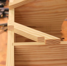
The technique begins by positioning the braces and transferring the profile to the top and end of the stool. The process is simple as long as you align the braces in the correct orientation. Then it’s a matter of tracing the edges of the braces using a sharp pencil (or marking knife, if you prefer).

After the layout is extended down the two faces of each part, saw on the waste side of the lines to define the socket. Next, cut the waste area into small sections around an 1/8″ in width, working from end to end of the socket. Stool_3Because one end of the socket is angled and the other straight, it’s better to slightly angle your saw position as you cut – I begin on the square end of the socket, and twist my angle as I work toward the angled end, all the while maintaining the 1/8″-wide sections. Make sure to cut to the base line and not any farther. Staying short of the lines means you’ll have more paring to do to clean-up the bottom, but going beyond the lines could result in making new parts.
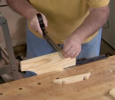
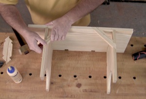
To break away the small sections, simply slide a chisel into the saw cut that defines one end of the socket. Stool_4That action alone should snap the sections right at the base line. I slip my chisel into the opposing end of the socket to make sure the sections are all loose. To complete the socket, pare the waste as you would a dovetail socket – be dead flat or a little sloped toward the middle of the board. With the waste removed, the braces fit in position and hold the stool square and strong.
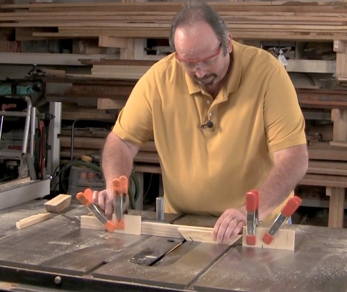
If you’re wondering how the braces were cut to shape at the beginning, that’s a nifty jig shown below. You can get the entire run down of the jig and how to set it up and use it when the 360WoodWorking site goes live. Sign up today.

Stool_Multicam_1.00_05_03_12.Still003

Build Something Great!
Glen

3 Comments

Filed under Uncategorized

Screw Gains

“Their usual solution was a pair of large screws driven forward through the side rail into the front leg to supplement the hidden mortise-and-tenon joint. Each screw fits into a drilled and carved out ‘pocket’ or ‘screw gain’.”

IMG_1248Immediately as I mention pocket screws, many woodworkers’ eyes roll back into the heads as if this method of joinery is totally unacceptable. Of course, there are places where the use of pocket screws is not the best choice. There are also places in woodworking where the joint is the perfect solution. It’s up to us to know the difference and where to draw the line.

But the more you discover about pocket screws, the more fuzzy the line becomes. I’ve been in million-dollar homes, standing in kitchens that easily cost six figures, and the face frames on the cabinets were pocket screwed. Perfectly acceptable? You betcha. But that’s not furniture, right? No it’s not, but the quote above is about furniture. It’s about great furniture. Museum-quality stuff. The quote is taken from the book by Robert D. Mussey Jr. titled, “The Furniture Masterworks of John & Thomas Seymour.” The Father and son team used pocket screws. This method of joinery is not a new concept conjured up by the Kreg company, but it has elevated pocket screws to a whole new level.

The reason I write about pocket screws this morning is that I have a decision to make on the lowboy I’m building based on the piece found at the Connecticut Historical Society.

IMG_0636The lowboy has no front rail at the top of the case – the drawers kick right up against the underside of the top. There is no room for wooden clips, and I hate “figure eight” fasteners. Therefore, to attach the top I need to be creative. Or not. The top on the original was nailed or pegged to the case. I’ve seen a number of antiques that have tops nailed in place, so it’s not out of the ordinary to do so. The problem I have is that at one of the pegs – it looks like a round dowel – the top has cracked. I’m not looking to repeat that problem, but I do need a secure top.

In one of the photos I have of the original, you can see a metal angle used to gain a hold. I don’t think that is how the piece was built, but a later addition. Not what I’m after. As a result, I’m turning to pocket screws. And while I have respect for the Kreg joinery setup, I’m looking for something more traditional.

Yesterday I scanned the above-mentioned book to find ideas. I had it in my head that most pocket screws holes in antique furniture were basically v-shaped cuts, then I re-discovered the Seymour pockets. Their pockets were rounded, tapered and neatly shaped. I had something to work toward.

IMG_1252My first attempt was using a carving gouge. I used a 9/20 fish-tail gouge to carve out a pocket (see the opening photo). It looked good, but was work heavy. As I studied the shape and design, I remembered a simple jig that I had built years and years back for use with my drill press, so I dug it out, dusted it off and made it work with a newer press. (On my older DP, the jig slipped over the table, but now I had to clamp the unit in place.)

The jig is built with its fence tilted back at a 22.5-degree angle. To align the workpiece, I position it at the intersection of the jig’s fence and base as it stands on an edge. The DP head and jig are arranged until the workpiece stands under the 1″-diameter drill bit so the back edge of the bit is even with the back face of the workpiece. Clamp everything secure. I then lay the piece back tight to the fence and add a couple of spring clamps as needed. To cut the rounded, tapered hole, drill as you normally do. (Play with the bit diameter and thickness of your workpiece to find the best results.)

Below is a test piece I made using all three methods. Each of the different pockets are aligned with the tools used to make those pockets. Which am I going to use? Easy. If you read the quote above, it states that the “screw gains” (fancy-speak for pocket holes) were drilled and carved. I plan to drill the bulk of the waste using the jig and drill press, then clean the gains with my carving gouge.

IMG_1251

Which method would you use?

Build Something Great!

Glen

11 Comments

Filed under Jigs, Joinery, Shop Tool

Circle-cut Moldings

High_Res ScrollI’ve returned to the Egerton tall clock this week to begin work on the hood moldings. Due to the dial design selected, this clock has a circular molding that is cut at an angle to fit to straight runs before it turns back the sides of the hood. I’m beginning with the arched section because it’s easier to produce a match when working on the straight runs, than it is to work up a perfect match on the arched section after the straight stock is made.

For this operation, I find it best to use my router along with a circle-cutting jig. You find the radius of the cut, which changes with each router bit used as you make the profile, then swing the setup as you make your cuts. IMG_1128For this clock, because there is a small added inlaid piece up the center of the hood, the arched molding is divided. That allows me to set up the stock as a pair of pieces instead a single piece with the entire arch cut. This translates into stronger moldings because there is no short grain where the piece can easily break.

In the photo above, you can see the setup. I have my router attached to a shop-made circle-cutting jig and yes, that is a drill bit I’m using as a pivot – no right-sized dowel in the shop. (Make do with what you have.) In the photo I’ve made the first pass, creating the thumbnail profile along the top edge of the molding. The workpieces are held with double-stick tape, as is the pivot platform.

The trick to this work is to properly set your router and the length of the jig to cut exactly where you need to produce the profile.IMG_1129 To do just that you need to accurately measure for the hole location (pivot point) on your jig. As you can see in the left-hand photo, you don’t need to be centered of your jig. As long as the measurement from the pivot to the correct edge of your router bit is right, your cut will be in the correct location. There are times when you’ll set to the far side of the bit and times when you use the near side to cut your profile.  Once determined, I use a bird cage awl to start my hole so the drill bit stays put as I drill. It takes some time to get the position just right, but it can be done.

IMG_1131The results are great if you use the correct router bits and get the setups just right. In the right-hand photo you can see the results of three passes using the setup. The first was the thumbnail. For the second cut I used a round-nose bit. The third cut was with a straight bit and it was simply to clear the material for the subsequent passes.

It was after the third pass that I realized I had used the wrong round-nose router bit. The width of the round-bottom trench was too wide for the profile as I had it drawn. You know what that means, right. Yep, start over. I’ll choose the right bits this time, and I think I’ll re-design the molding somewhat; I wasn’t thrilled with how it was coming out. Also, because it is time-consuming to accurately position the jig, I’ll switch to my Micro Fence circle-cutting jig which allows me way more accuracy as I work.

That’s my Sunday (another day in the shop, yeah). What are you planning?

Build Something Great!
Glen

Leave a comment

Filed under Jigs, Routers, Tall Clock