LVL Desk in a Weekend

Steve's deskIt’s a holiday weekend. Yeah. I have an extra day in the shop on Monday that I intend to fill building a quick desk with my younger brother. He’s looking for something a bit toward contemporary and I’ve sold him on using LVL (Laminated Veneer Lumber) for the top with legs that are simple to make; he wants inexpensive and quick. The most time spent – at least I hope it takes longer than other parts – is time building a pencil drawer.

I took two hours to rip, square and assemble the pieces of LVL for the top one night after work. That includes time spent watching glue dry. The process is easy. Here are the steps in case you want to play along (or build something similar down the road).

2M4A2152I began with two LVL beams that were 1-3/4″ x 11-7/8″ x 10′-0″. After chopping the beams in half lengthwise, I set up at the table saw to rip each piece to 2-1/8″. Of course, one edge was ran over the jointer to give me a square edge to start. Using a 50-tooth combination blade, LVL cuts easy. The beams I purchased had a bluish painted surface, as you can see in the photo. That worried me little after making the jointer pass. Then after ripping the pieces and turning them on edge, you begin to see the final surface. To make up the 30″ in width needed to the desk, I ripped all four half beams, which produced 20 strips that were 1-3/4″ x 2-1/8″ x 60″+.

2M4A2153
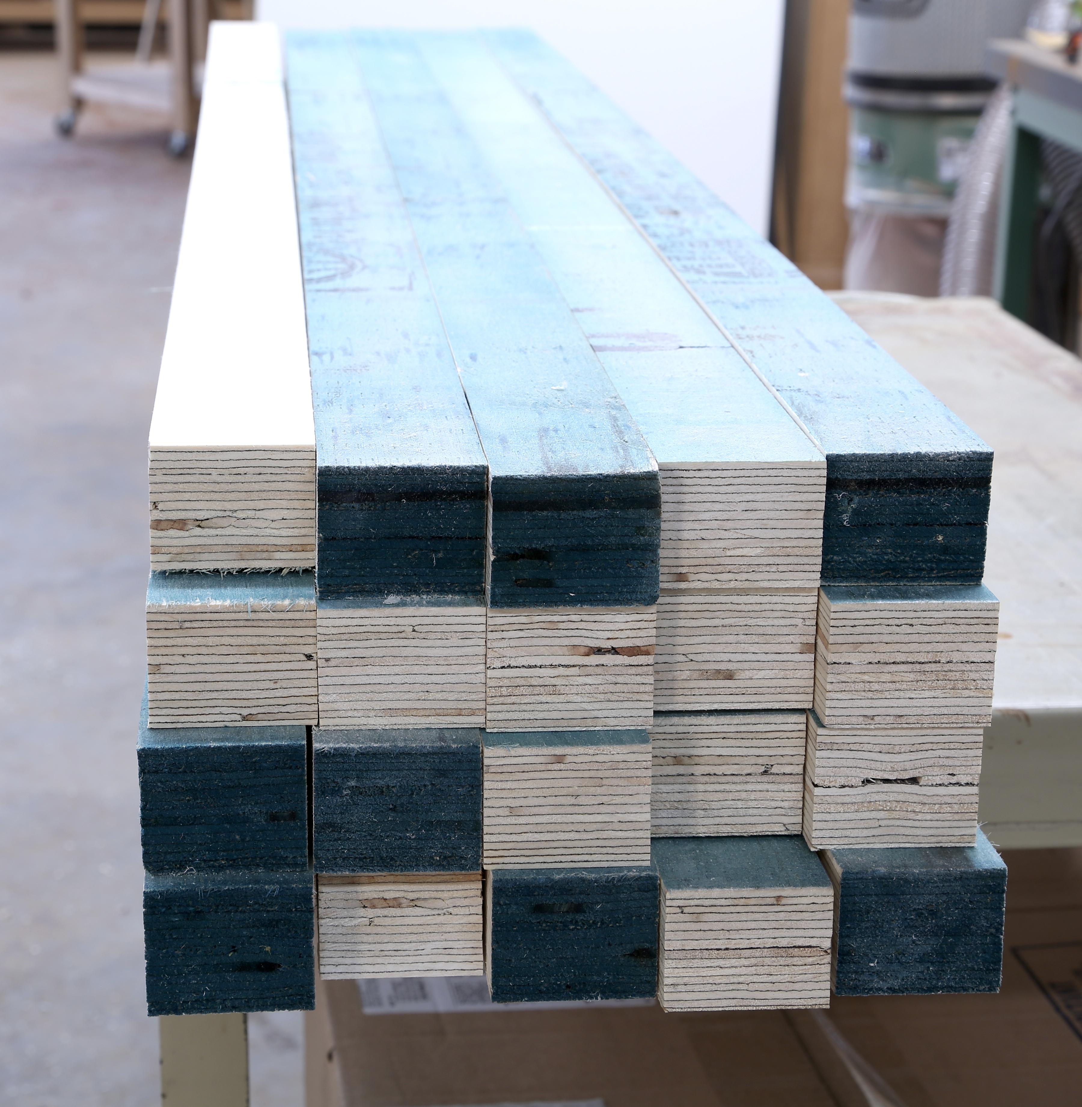
From the table saw, I returned to the jointer to true one of the two yet-painted edges to provide a solid glue surface. A single pass flattened all but two of the pieces. Those two pieces were areas where the lamination overlapped causing a bump in the face. I ran them a second time in order to achieve a flat face. You still see bluish paint in the left-hand photo because only one face has been flattened (all faces run over the jointer knives are downward facing, waiting for the planer.

2M4A2156A ride through the planer was so easy. All I needed was to flatten the second face for glue. The planer I used is setup with a spiral cutterhead. Even though there were no problems with the three-knife arrangement at the jointer, the planer surface was smoother. (This is why, when asked, I suggest that the planer have the spiral cutter, but it’s not that important on your jointer – the jointer is seldom the last surface of your work.) The first pass was great except for, you guessed it, the two pieces that needed the extra pass at the jointer. When those two were feed through the planer, the final surface was untouched in a couple places. A send pass through the planer was required, but only for those two pieces.

To my surprise, the most difficult process in assembling the two planks for the top was the glue-up stage. Spreading glue on the 19 pieces (yep, I had one strip left over after attaining the 30″ width) was a pain. 2M4A2159I decided to lay the strips out as if I were gluing panels for a case side. With the finished face up, I then rotated each piece to a glue face. With the pack tight together, I squeezed glue up and down the face leaving small lines covering the surface. I spread the glue using a thin scrap of wood. Scraping along the length was no good, but across the pieces worked like a charm. With one side gooey, I flipped the strips abd slathered up the second side. I was amazed at how sticky the pieces were as I tried to align the ends – I needed a mallet to move the individual pieces. Than goodness I assembled the 19 pieces in two separate groups. When finished, I added clamps and let the half-tops set. All in all, I used almost 3/4 of a quart of glue.

Out of the clamps in 45 minutes and all that was left was to clean the squeeze-out off and make a pass through the planer to level the two surfaces. When slid together – I still need to assemble the two halves – you get a good idea of how the top looks. My guess is it’s even better when a bit of finish is applied. Next week I’ll walk through the legs. Get it?

Build Something Great!

Glen

2M4A2161(1)

2 Comments

Filed under Desk Build, Methods of Work, Power Tools, Shop Tips

Best Glass Cleaner

IMG_1878Here’s a quick tip to clean glass panes or windows. Forget Windex Glass Cleaner. Forget those local community car washes that use newspaper to clean car windows. The best way to clean glass is with – wait for it – steel wool. That’s right steel wool. There’s no need for any liquid cleaner, but you have to use the right steel wool. You should use #0000 (four aught) steel wool.

I learned this tip from a friend years back. He was in the automotive repair and body shop business and was forever cleaning windows. At first, I thought he was pulling my leg (that’s Midwestern for joshing me, kidding me or otherwise telling me stories). As soon as I got back to the shop, however, I gave it a try. The results are great. I never turned back to any other method for cleaning my glass windows. Give it a try on your home windows, too. But make sure you’re not scrubbing any UV film coverings.

Build Something Great!

Glen

1 Comment

Filed under Back to Basics, Methods of Work, Shop Tips

Four-squared Boards

2M4A2095I needed a single board for a project that I’m building in an upcoming issue of Popular Woodworking Magazine. The only surface I need to look good is the front edge which faces the front of my cabinet. With no milled lumber available other than a few natural-edge cutoffs, I laid a straightedge on two of the cutoffs to remove the natural edges, made cuts at a band saw, jointed the edges and glued the two boards together to make one. A great method to stretch lumber on a project.

As I assembled the pieces, I thought back to classes in which I’ve taught woodworkers proper milling techniques using machines. Step one is to flatten a face. In my system, step two is to use a thickness planer to create a parallel face. For some woodworkers, step two is to square one of the edges while at a jointer, but I disagree. If you square an edge, does that edge remain square as you flatten the second face, especially while flipping the board end-for-end during the milling process to keep the exposed surfaces at equal moisture content? There’s a chance that it doesn’t – if your board rides up on an elevated edge of the planer bed, or if a small chunk finds its way under one of the corners as you send the piece through the planer, you could change the squareness of that edge of the workpiece. That makes step three, for me, to then create an edge that is square to both faces. It’s at this point that I often run crossways of students in the class.

Many woodworkers feel that it’s necessary (step four) that you rip the board at the table saw. Is it? The answer is that it depends. If you’re simply joining two or more boards in a panel glue-up, it’s not important that the boards are ripped into a four-square configuration. Why waste the wood. Make your step four at the jointer. In fact, one of the best techniques for hiding seams when assembling panels is to cut a board for a better grain match, which removes the four-square measurements from your board. If however, you’re preparing a board for use in your project, then make your step four at a table saw. You need to think through operations and not simply be guided by a set of rules. We all know that rules are to be broken.

If you’re preparing your lumber using handplanes, you need to go about the work differently. You also need to answer a question for me – what the hell is wrong with you? Milling lumber is grunt work. Use a machine for the grunt work and use your handplanes for finish work. C’mon man!

Build Something Great!

Glen

3 Comments

Filed under Back to Basics, Methods of Work

Tall Clock Fast Finish

IMG_1874If you’ve followed this blog for anytime at all, you know I’ve been working on two tall case clocks. I’m happy to say that one of the clocks is done. Mine! Why is the clock I built for me complete and the other for a customer not yet finished? The answer is two-fold.

If you watched any of the episodes of the New Yankee Workshop, Norm always built a prototype. Even though I was building two clock simultaneously, I worked out the details on  the clock I was building for myself before moving to the customer’s clock. (Believe me, there were quite a few adjustments along the way.) As a result, their clock is much better. I experimented on inlay, door design and most recently on how to best position the hood door; it took two attempts to get the location right.

The second reason my clock is complete while the customers languishes on is due to the clock dial pan. Many of these antique clocks had hand-painted dials. We’d talked about the dial many times, but it wasn’t until recently that final decisions were made as to what would be painted. With a decision made and the painter contacted, the customer’s dial should be completed in November. Step_1I, on the other hand, have not yet determined what I’d like to have painted on my dial. So how did I get my clock finished? I cheated.

I visited an antique clock dealer’s web site, selected a clock that I liked, checked that the dealer had shown a front-on view of the painted dial (where the red arrow points), then copied the dial into my computer. You can see the page at the right. (If you click on any of the photos, they will enlarge for a better view.)

Step_2Once the dial was loaded, I went in and stripped the interior of the image out using PhotoShop – I’m not overly experienced with this program, but I squeeze by. I pulled the interior out because I have a movement complete with hands that I want to use, so there was no need for the hands. Also, don’t have a sweep second hand (the miniature dial just below the XII) although those are very cool in antique clocks. Lastly, I didn’t want my clock signed by Aaron Willard from Boston (not that I wouldn’t be thrilled to own such a clock). With those steps complete, I manipulated the image to match the dial pan size and hit the print button.

And in case you think I’m pulling one over on you, below is a photo of my clock with the hood off. When I figure out the painting for the dial, I’ll make the change. But until then my paper cheat is going to work fine.

Build Something Great!

Glen

IMG_1875

4 Comments

Filed under Tall Clock

Hole in the Round

IMG_1867I learned this trick way back when I transformed countless wooden knobs into cupboard turns. I needed to drill the rounded portion or tenon of the knob – the part that generally was glued into the door or drawer – so I could insert a short section of dowel that would extend through the door. That dowel would have a wooden finger attached that would turn down onto a small wedge attached to the backside of the door. I could have simply purchased the turns, but the knob design seldom matched the other wooden knobs used on the piece.

Today, while using more brass than wood for pulls, knobs and turns, I use the technique only sparingly. But it’s a great technique when you need it.

IMG_1868Begin by drilling a hole into a scrap that is sized to the diameter of the rounded object; generally that would be the knob tenon when making a cupboard turn. In this case, I’m drilling a hole in the center of a dowel, so in my example, I’m drilling the diameter of the dowel (shown at right). Drill the hole deep enough to allow the base of the knob, if that’s what you’re drilling, to sit flat against the scrap. (You should do this with a drill press to make sure the holes are straight and true.)

Change drill bits to the diameter of you’re new hole, and drill clear through the scrap using the center of the first hole as a guide to align the second hole. The idea is that the first hole holds the piece to be drilled in place and the second hole locates the exact point of the new hole. To put this in terms of drilling out for cupboard turns, the knobs would have a 1/2″-diameter tenon into which I would fit a 7/16″-diameter post. There was little room for anything but exact alignment.

IMG_1865To use the setup, insert the tenon, or short piece of dowel in this case, into the appropriate diameter hole, align the drill bit with the second diameter hole (as shown at the left) and drill down. It’s that simple. Plus, every time you use the jig, the results are the same (as shown in the opening photo). And it doesn’t matter what diameters you use, as long as the second hole is smaller.

Put this trick into your pocket. Some day it will come in handy.

Build Something Great!

Glen

4 Comments

Filed under Jigs, Methods of Work, Shop Tips

Confidence is Key

Cherry Highboy copyA show about stained glass made my dovetails better. Yes, it’s true. I’ve told the story many times, but I don’t recall if I’ve written it in this blog. Here’s the abbreviated version. I was deep into watching a TV show about stained glass. As I watched, I was amazed at how easy stained-glass makers cut and broke the glass they used. Grab a good-quality glass cutter, etch the outline of what they wanted then snap the piece free right at the line no matter what its shape. They had confidence.

The next day while in my shop facing a stack of 11 drawers for a high chest of drawers ready to dovetail (shown above), I decided that I too should have the confidence to cut dovetails better and quicker; I had to find and use that confidence. That day I completed all 11 drawers and they were the best dovetails that I had ever cut. Confidence is the key.

IMG_1842Since that day, I have had confidence in cutting glass as well. I know it’s going to snap at the etched line. That’s what it’s suppose to do. Yesterday, I put my confidence to the test. I cut the glass to fit the tombstone design on the Egerton hood doors. Plus, to make the job even more challenging, I used reproduction glass that has waves and imperfections in the glass.

Adj_Door copyThere is a key to making this work. The secret is in the door. Take a look at the backside of the door (you can see it better in the inset photo). If you look close, you’ll see how the corners of the frame are rounded. Years ago I tried to keep those corners square – that was almost an automatic failure when cutting this design for a door. (I did have a glass expert cut a panel for the first hood door I built and he used a sander to square the corner.)

IMG_1846To get the glass cut to fit, I begin with a panel that’s sized to fit the width and is cut to the final length but without the tombstone cut. Next, lay the rectangular sheet into the door frame with its bottom edge in the frame and the top section riding just above the arched portion of the door. From there, take a permanent marker and trace the design of the tombstone door onto the piece of glass; complete both halves (the apex of the arch should terminate at the top edge of the cut glass panel.

IMG_1848Now it’s time to make the cut. As I score the glass, I listen to make sure the cutter is etching the glass. If you do not hear the etching noise, you’re not going to make this work. With the glass scored, it’s time to put to use that ball shape that’s on the non-business end of the cutter – before I began cutting glass, I wondered what that ball was for. To snap the glass, hold the corner firmly with a slight downward pressure then tap the underside using the ball end. If you watch closely, you can see the etch turn into a break right at the scored line. Be patient, but have confidence.

IMG_1849In a short amount of time, the piece snaps off and you’re left with half of the tombstone top cut. The first half is the easiest because if you don’t complete the job, you begin again. The second cut is when you need to summon all your confidence. If the second cut breaks in a less-than-acceptable location, you toss the panel and the completion of the first half. But with your confidence at an all time high due to the adrenaline pumping through your body with the first half cut, you cut and snap the second half in no time. All that’s left is to make sure the piece fits the door. (I had to nip a small piece off the second piece of tombstone glass cut for door #2.)

IMG_1850

I have two small square pieces of glass that also fit into the hood. After the tombstone cuts, square cuts are a snap. That’s glass-cutting humor.

Build Something Great!

Glen

4 Comments

Filed under Methods of Work, Tall Clock

A Teaching Week

The past two Sundays (the day I regularly post) I was either on my way to the Connecticut Valley School of Woodworking, or on my way to New York city for a day at the Metropolitan Museum. Today I’m sharing photos of the class. In coming posts, I’ll share photos from the Met and from the Connecticut Historical Society – where we first discovered the class project (read more about that here).

IMG_1835

Class began with a brief discussion of how to pull leg patterns from photos using SketchUp, then the class made patterns and began their legs. IMG_1777After layout, everyone took turns at the band saws so they were immediately plunged into leg work.  In expectation of the legs taking two days to wrap up, head schoolmaster Bob Van Dyke arranged a trip to the Connecticut Historical Society (CHS) for Tuesday afternoon. (If you haven’t had the opportunity to visit CHS, do yourself a favor and do so. The staff is first rate and CHS is very reproduction-craftsman friendly.) If you plan to build this lowboy from the article in Popular Woodworking Magazine (February 2014, #209), I suggest that you take an extra 1/8″ off the leg pattern before you begin. When I saw the original lowboy at CHS for the second time, I realized that the legs on the antique lowboy were much finer, giving it a lightness that I missed while sizing from the many photos I had.

IMG_1781After the legs were shaped so far, a trip to the lathe was in order. Turning the feet and pad took a long time for the class – seven class members was 28 individual feet to turn. Everyone survived without problems, Right Jon? Here you can see Janice using pair of outside calipers to bring the foot to diameter. In all we used two caliper setups and only four or five basic turning tools. And it was nice to have a variable-speed lathe to work on; there’s a lot of wobble when you first turn the leg to shape the foot.

IMG_1801From the lathe the next step was to mortise the legs for the aprons, back and ends. While this work can be done while the leg is still as a blank, I think it’s better to actually see what the leg looks like before making a call as to where it will fit. After the legs are shaped, you can easily see which legs look best – those go to the front, while others move to the back. We had two mortisers setup and working, plus I demonstrated how to use a plunge router to do the work. Of the seven taking the class, only one used a plunge router for his mortises. (It’s great during classes to use tools you don’t have in your shop, as long as you know how to do the work when you’re at home.) One additional hint is to make sure that you’re cutting to the necessary depth – a couple of woodworkers had to make a return trip to the mortiser. Sorry I didn’t catch that sooner Mike.

IMG_1813By Wednesday everyone had knocked out the remaining outside case pieces and the lowboys were beginning to take shape. Jon spent extra time on his legs – he also noticed the finer look of the lowboy at CHS. After cutting the designs for the ends and front apron, we worked on bending the cock bead. I was happy that the bends for the longer end-panel beads went so well. Most everyone got those pieces bent using a soaked piece of wood and a heat guy set on high – if you take your time, you can feel the wood give up as it melts into position. If you apply the heat for a bit longer, you actually set the bend just as if you left a steamed piece in the mold until it dried. Smaller, tighter pieces were made using a router with a specifically paired guide bushing and router bit. (Read the article to learn the setup.)

IMG_1820Work on the inside of the lowboy went smooth, aside from the occasional misplaced screw pocket. There were a couple of hand-cut dovetail sockets that needed attention, but overall the class breezed through the interiors. As the cases were coming along, the lowboy tops came into focus. A little router work was all that was needed. It took, however, two passes around the top to get the profile complete. And with this project, the profile continued on all four edges; I checked the original lowboy to make sure. Many tops from the period are molded only on three edges.

IMG_1825Late of Friday and most of Saturday, drawers were the topic at hand. Of the seven in the class, three decided to build the drawers with the slanted sides and back – a challenging task even if you’re experienced in dovetail work. As you may have guessed from the opening photo, not all the drawers were completed during the class. As it is with many classes, there is homework. Also, most of the class members decided not to glue up their lowboys. Flat-packing the pieces home is much easier than trying to cram a lowboy into the back seat.

The class went great. I worked with a lot of talented woodworkers. I’m amazed at how good many of the folks are who take classes. If they had more time in the shop, their work could easily rival many of the top woodworkers in the country. Take a class. It’s fun and it’s sure to improve your woodworking.

Build Something Great!

Glen


8 Comments

Filed under Uncategorized

No Day to Spray

AntiqueBackWhen I got up on Saturday morning, I knew there was a huge possibility that in the shop I wouldn’t be doing what I planned. I was going in to spray the final coat of shellac onto my clocks; I’m looking to darken the overall appearance just a shade more. The humidity was high which means that there was a chance for the finish to blush, or turn cottony white with moisture trapped in the finish.

Instead, I decided to work on the backboards for the two clocks. On most antique clocks, the backs run top to bottom and are not attached to the hoods, so the hood can be removed. The stacked series of three photos at the left show a typical clock back (click on the image to make it bigger).

Generally you see a main board that runs the full length with ears attached at the base and hood areas. That requires a board or panel that’s 90″ in length and 15″ wide. I could have done that – may due it if John and Joe (brothers for which I’m building this clock) want to go with the antique design.

The second clock, however, is for me (at least at this time), so I’m going at it differently. IMG_1767I’m running the boards across the back from the bottom up about 50″ just as would be seen on a case piece of furniture. I then plan to turn the upper board so its grain runs vertical. To make the transition, I’m using a tongue-and-groove joint. It’s a bit more work and will need a few additional fasteners (nails I suspect), but I can use short pieces of scrap cut off from other projects. Frugal, huh!

To make this happen, I first added a shiplap cut to each of the milled, over-long, random-width boards selected for the back. IMG_1768I began at the bottom – the bottom board was cut on only one edge. From there to the 50″ mark (it doesn’t have to be that length, it’s just what I chose based on the number of pieces I had to use and the width of those pieces), I fit and positioned each board. The top board – also shiplapped on one edge – was taken back to the tablesaw for the tongue portion of the transition joint. I then slipped the top horizontal board in place and added a couple of clamps to hold things secure.

IMG_1771I had to get the final length measurement of the vertical board, so I had to stand the case upright and add the hood. With that measurement in hand, I cut the groove portion along the bottom edge of the panel, and laid out the exact spot where the back needed to step out to fill in the extra width of the hood.

Because the glued-up panel had set in the shop for some time,there was a small amount of warp I had to deal with. Here’s a great shop tip: To straighten out the panel, I clamped a straight piece of stock across the panel width keeping the clamps above the height of my saw fence, then made the cuts needed to form the groove.

The ears were cut at my band saw, then trimmed to length at the bench using my handsaw. To final check and tweak the fit, I joined the tongue and groove, then slide the assembly into position. Below you can see how the transition works. Because the top panel extends down the clock’s case, there are more than enough places for fasteners. This setup should work great.

Build Something Great!

Glen

IMG_1775

1 Comment

Filed under Design, Joinery, Methods of Work, Shop Tips, Tall Clock

Hood-door Hinges

IMG_1746When you think about hinges for furniture, you probably think about regular hinges with two leaves that are screwed to a door and to the case or face frame. That’s not the case with many hood doors on tall case clocks. The opening photo shows two pairs of hood-door hinges. No knuckles. Just a flat piece of brass cutout in a funny shape. These hinges are different.

HortonI picked up my hinges from Londonderry Brass ($15.50 each). These hinges have a nice antique look about them, but there are a few problems with which to deal. Horton Brasses’ hood-door hinges ($10.00 each) are less antique looking, but do away with some of the problems. (My third primary hardware supplier, Whitechapel LTD., didn’t have the hinges or I was unable to track them down on the web site.)

If you look at the photo above, you get an idea as to what the problem is with the hinges. The company sends out hinges that are all the same. Unfortunately, you need matched pairs. Also, the holes in the hinges are too small for appropriate screws. The first order of business for me was to align the hinge plates into pairs, enlarge the holes and make countersinks for the heads. (I marked the face that needed the countersinks.) The work is easy because the brass is soft, but due to the odd hole locations presented with the antique look, the enlarged holes get dangerously close to the outer edges of the hinge. If I could get these hinges without holes and countersinks, I think I’d be better off. In fact, if I had the time (and inclination to do so), I may try cutting my own from a piece of sheet brass.

IMG_1757How these hinges fit is also different. The work to set the hinge is all in end grain – the top and bottom end of the hood-door stile. As you locate the hinge, you need to watch the edge of the door stile. A strong rap with your mallet and the chisel can easily break the grain along the edge of the door. That’s not good or fun, so work with a knife or cutting gauge and leave the whacks for dovetails. And you better sharpen your chisels before you begin. Of course, you know what it’s like to pare across end-grain.

IMG_1761After you get the hinges set into the door stile – one at the top and a second at the bottom – the screws are installed. Because I’m merely fitting these at this time (I have more finish work to do), I installed only two screws per hinge. A bird-cage awl is the perfect tool to start these screws. Here you can see where having the holes too close to the edge of the hinge can be problematic. In early builds, I’ve split the stile as I’ve driven home the screws. Make sure you properly drill the holes, especially at the outer edge.

IMG_1762With the hinges installed, how things work is rather simple. The part of the hinge that extends out from the door is secured to the hood with a screw through the hole. Originally, that was probably done with pins, but I think a screw is a better choice in case you need to pull the door for any reason, such as to replace the glass. This method also allows you to align the door in the opening. Set the door at the bottom then as you install the top screw you can make slight adjustments to get the reveal just right.

And here’s a tip when working with hardware that shows more handwork. Mark the individual hinges so you can get them back in the same place. I learned this lesson the hard way when I built my first step-back cupboard using rat-tail hinges. As I we back to re-install the hardware, I spent too many extra hours trying to fit the parts into the proper position – all leaves are not the same, and the screw holes are not matched. Sharpie to the rescue.

Build Something Great!
Glen

IMG_1763

Leave a comment

Filed under Hardware, Shop Tips, Tall Clock

Inlaid Box #4

IMG_1752I’m sure you’ve heard the saying “never send a boy to do a man’s job.” That holds true for magnets, too. After hinges were added to the inlaid box, I drilled and installed two rare-earth magnets to hold the lid closed. Working in only 1/2″-thick material, I decided to use smaller-diameter magnets. After drilling the first hole and wanting the two magnets to line up, I used a 23-gauge pin as a center finder to mark the lid location for the second magnet – it worked like a charm. I epoxied the magnets in place and went home for the day.

CombinedA

The next day, I dropped by the shop on my way to work just to check my magnetic lid setup. The magnets looked great. They were perfectly aligned. There was not enough pull, however, to hold the lid closed. Crap! Now I’d have to pull those magnets, repair the box and lid from the destruction of pulling the magnets and come up with another option to hold the damn lid closed. I thought about it for a couple days then decided to stay with the magnets, but increase the size. Go big or go home, I guess.

IMG_1747With the repairs made and the two magnets holding strong, I was ready to apply a finish, so I mixed up a little oil/varnish finish for the box. I’ve used this finish on many pieces of furniture, including a Shaker sewing desk and a Seymour marble-top sideboard. It’s easy to make and easier to use.

Mix 1/3 boiled linseed oil, 1/3 spar varnish (spar adds a bit of elasticity to the finish) and 1/3 turpentine (I’m told you can use mineral spirits as well, but I’ve never done so). That’s it. For larger jobs, I mix enough for 1-1/2 coats, then eliminate the turpentine (50/50 varnish and oil) as I add to the mixture. The turpentine simply thins the mixture so it can soak into the grain; you only need this on the first coat.

Finish

Brush the mixture onto the project and keep everything wet for about 5 minutes so the finish gets deep inside the wood pores. After five minutes, wipe away the excess. If there’s no excess, you didn’t apply enough finish. Let the project sit until the finish is dry, then apply another coat. On later coats, because the finish is only oil and varnish, you need to let things sit until the mixture feels like honey before wiping off excess. And if you missed a spot when wiping things clean or if you have a rough texture in the dried finish, take #320-grit sandpaper and sand the surface smooth.

The opening photo shows the box with its first finish coat applied. It takes three coats to build a protective finish, four coats starts to build a sheen and with each additional coat, the surface becomes even more shiny. Like I said, easy.

Build Something Great!

Glen

5 Comments

Filed under Finish Techniques